



Piny limitujące formę dla form samochodowych: Ładunek, Zużycie, oraz precyzję
Mold limit pins for automotive molds act as mechanical stops. They establish or restrict the travel of an ejector plate, slider, side action, or another moving mold component. Their performance depends on more than pin diameter or material. The stopped mechanism, Prędkość kontaktowa, pin support, Powierzchnia łącząca, Rozkład obciążenia, and required endpoint all affect the result.
Piny graniczne należą do szerszego systemu Standardowe części formy (wnioskowane), but they should not be selected using broad catalog criteria alone. A suitable stop must carry the intended reaction without bending, loosening, damaging the mating plate, or gradually changing the mechanism’s final position.
There is no universal pin diameter, Twardość, Dopasowanie, or replacement interval for every automotive mold. Selection starts by defining the movement being controlled.
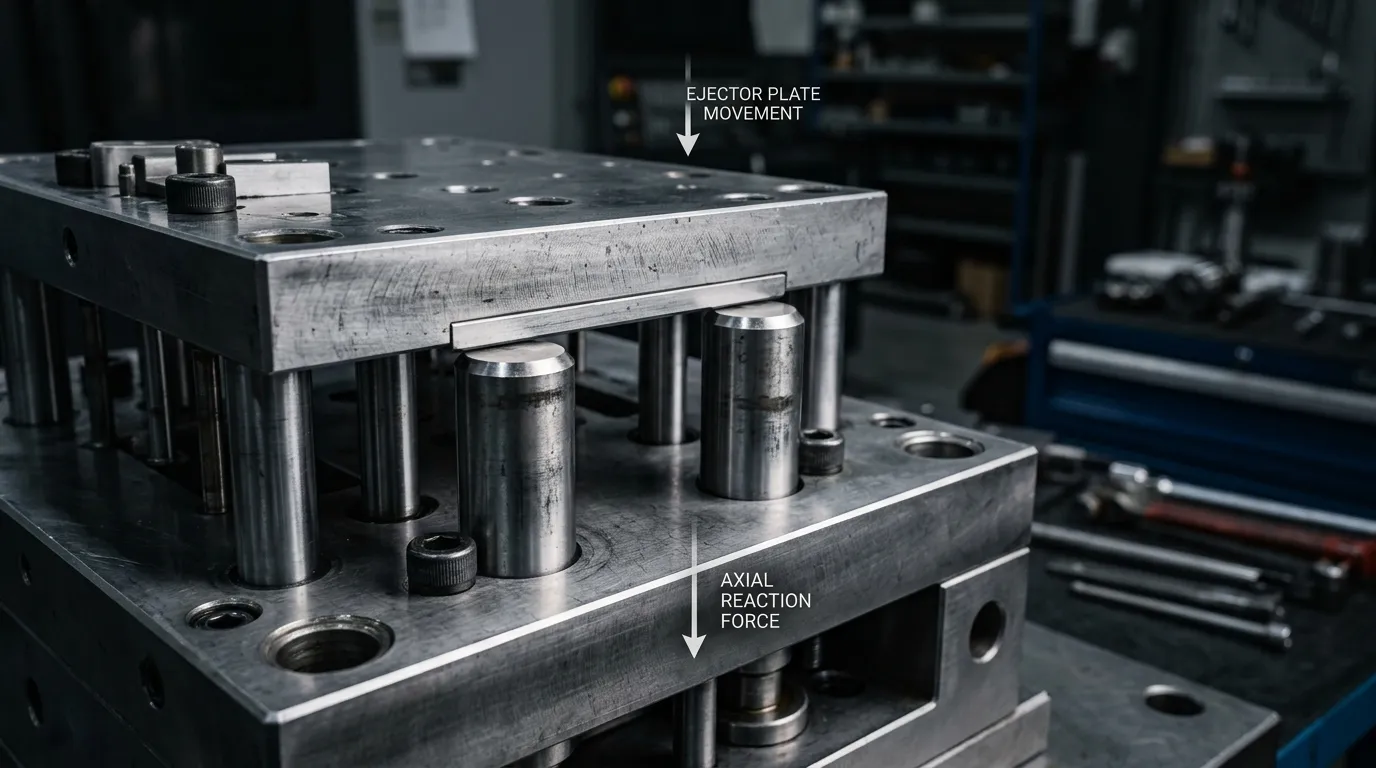
Co kontroluje pin limitujący formę — a czego nie
A mold limit pin is a fixed mechanical stop. When the moving mold component reaches the designed endpoint, it contacts the pin or a surface supported by the pin. The stop reaction then passes into the mounting plate and surrounding mold structure.
“Limit pin” and “stop pin” are often used for similar components, but supplier terminology is not always consistent. The drawing should therefore state the actual function:
- which component moves;
- the direction of movement;
- the required endpoint;
- which surfaces make contact;
- whether the stop sees gradual loading or repeated impact.
A limit pin should also be separated from other cylindrical mold components.
| Składnik | Główna funkcja | Typowa interakcja | Główna kwestia selekcyjna |
|---|---|---|---|
| Sbolec graniczny lub zapórnik | Ogranicza podróż w określonym końcu | Ruchoma płytka lub mechanizm styka się z ogranicznikiem | Contact load, Wsparcie, zużycie, and effective stop length |
| Sworzeń prowadzący i tulejka | Prowadzi i ustawia sekcje formy podczas ruchu | Sworzeń prowadzący zazębia się o dopasowaną tulejkę | Przebieg trasy, Zaangażowanie, Dostęp, Smarowanie, i noszenie |
| Sworzeń wyrzutnika | Wypycha odlewany element z wnęki lub rdzenia | Czółek sworzni styka się z formowaną częścią | Ejection force, placement, surface marks, and retention |
| Return pin | Zwraca lub resetuje zespół wyrzutnika | Zamykanie formy lub mechanizm powrotu przesuwa system wyrzutnika do tyłu | Return stroke, interference, and reliable reset |
| Blok graniczny | Zapewnia szerszy mechaniczny ogranicznik | Płytka lub mechanizm styka się z większą powierzchnią ogranicznika | Obszar kontaktu, space, Wsparcie, and replacement access |
Guide pins and bushings are responsible for guided mold movement and mold-half alignment. Their design belongs to the separate subject of Sworznie i tuleje formowe. A limit pin may help maintain a repeatable mechanism endpoint, but that does not make it a substitute for a guide system.
Zdefiniuj mechanizm formy samochodowej przed wyborem stopu
The first design question is not “Which pin size should be used?” It is “What movement must be stopped?”
An automotive mold may contain several moving systems, each with different loading conditions:
- an ejector plate reaching the end of its stroke;
- a slider reaching its open or closed position;
- a side-action mechanism stopping after core withdrawal;
- a moving support or auxiliary plate reaching a controlled endpoint.
Before selecting a stop, Definiuj:
- The moving component and its direction of travel.
- The total stroke and required final position.
- The moving mass.
- The expected velocity when contact occurs.
- Any hydraulic, spring, Maszyna, or mechanical force still acting at the endpoint.
- The number and location of stop points.
- The available plate thickness and pin support depth.
- The mating-surface material and contact geometry.
- Access for installation, inspekcja, adjustment, and replacement.
- Any OEM, Tier, or customer-specific tooling requirements.
Automotive customer specifications may set their own rules for mechanical stops, Płyty zużycia, Systemy prowadzące, movement controls, Materiały, or documentation. Those requirements should be checked before generic design guidance is applied.
Ograniczniki płyty wyrzutowej
An ejector plate is usually broad and relatively stiff, but it may still deflect under load. If several limit pins are used, their position and effective height affect how the plate reaches the endpoint.
A practical ejector-plate stop arrangement should consider:
- whether the stops are distributed around the loaded area;
- whether the plate can contact all stops at nearly the same time;
- whether one region of the plate bends before another;
- whether the stop reaction is transferred into adequately supported mold structure;
- whether the pins remain accessible after assembly.
If one pin is slightly taller or better supported than the others, it may contact first and carry a disproportionate part of the reaction.
Suwak, Side-Action, and Moving-Plate Stops
Horizontal or angled mechanisms introduce additional concerns. A stop pin may receive side load if the slider is not guided correctly or if the contact faces are not square to the direction of travel.
For these mechanisms, Sprawdź:
- whether the stop controls the open or closed position;
- whether the contact is axial or angled;
- whether a wear plate or replaceable insert is needed;
- whether an adjustable endpoint is required;
- whether dirt, Smar, or molding residue can enter the contact area;
- whether the stop can be inspected without major disassembly.
The guide system should control the path of the slider. The stop should control its endpoint. Combining both functions in one unsupported pin increases the risk of bending and uneven wear.
Jak ładunek przechodzi przez system pinów granicznych
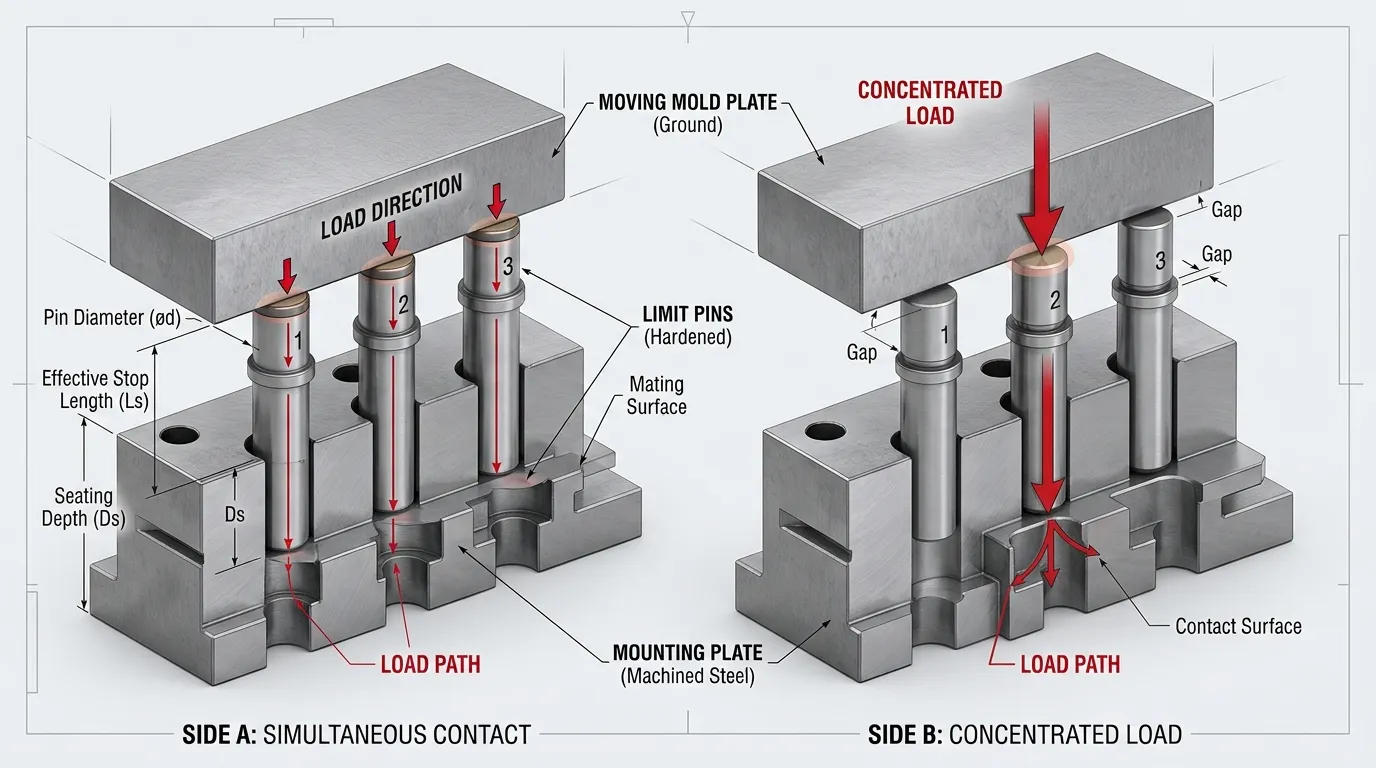
A limit pin does not carry load independently. It is one part of a load path:
Mechanizm ruchomy → powierzchni styku → sworzeń graniczny lub ogranicznik → gniazdo sworzni → płytę montażową → strukturę formy
Every part of that path must support the reaction.
A pin loaded directly along its axis mainly sees compression. A pin contacted off-center or at an angle may also see bending. Bending becomes more significant when the exposed length is large, the mounting support is shallow, or the contact force is not aligned with the pin axis.
The mating surface matters as much as the pin. A small pin end creates a concentrated contact area. Even when the pin itself remains intact, the opposing plate may indent or wear. That indentation changes the effective stopping position.
The surrounding plate must also be stiff enough to support the stop. A strong pin mounted in a thin or flexible plate may still produce inconsistent contact because the plate deflects.
Kontakt statyczny kontra uderzenie na końcu suwu
A mechanism that settles gradually against a stop creates a different condition from one that strikes the stop at speed.
| Stan kontaktu | Główne cechy | Kwestia selekcji |
| Kontakt stopniowy lub statyczny | Obciążenie rośnie powoli i może pozostać na końcu | Kompresja, plate support, long-term indentation, oraz stabilność |
| Wielokrotny kontakt uderzeniowy | Masa poruszająca się dociera do zatrzymania z mierzalną prędkością | Impact severity, Wytrzymałość, loosening, deformacja, and mating-surface damage |
| Kontakt kontrolowany lub tłumiony | Ruch jest spowalniany, zanim dotrze do mechanicznego zatrzymania | Residual force, control reliability, and emergency stop capacity |
Moving mass and contact velocity influence the energy reaching the stop. Deceleration distance, damping, machine control, and structural flexibility also affect the contact condition. A final pin design should not be approved from static force alone when repeated impact is possible.
Dlaczego wiele pinów ograniczających może nie dzielić obciążenia równomiernie
Using four stops does not guarantee that each carries one quarter of the load.
Unequal sharing can result from:
- small differences in effective pin height;
- uneven seating;
- plate deflection;
- non-parallel contact surfaces;
- asymmetric stop placement;
- different support stiffness beneath each pin;
- wear or indentation at one contact point.
The tallest or stiffest-supported pin may contact first. It then begins carrying load before the other stops engage. Z czasem, this can create a repeating pattern: one pin wears or indents faster, the endpoint shifts, and the remaining pins begin contacting under different conditions.
Effective stop height, Miejsca siedzące, plate stiffness, and contact pattern should therefore be evaluated together.
Geometry, Materiał, and Fit Determine Wear and Endpoint Stability
Catalog dimensions describe the part, but they do not fully describe its performance. Średnica, effective length, exposed length, mounting fit, Geometria kontaktu, Stan materiału, and the opposing surface all influence the stop.
Średnica, Effective Length, and Unsupported Length
Several dimensions have different functional roles:
| Wymiar lub cecha | Efekt funkcjonalny |
| Średnica sworzni | Influences stiffness, bearing area in the mounting hole, and resistance to bending |
| Całkowita długość | Definiuje całkowity rozmiar komponentu, ale może nie być równy funkcjonalnemu wymiarowi zatrzymania |
| Efektywna długość zwarcia | Kontroluje końcowy mechanizm końcowy |
| Długość bez podparcia | Wpływy na wrażliwość i sztywność na zginanie |
| Głębokość siedzeń | Wpływa na wsparcie i stabilność pozycji |
| Geometria końcowa | Kontroluje powierzchnię styku i ciśnienie lokalne |
| Cecha barku lub retencja | Affects seating, Zgromadzenie, Usunięcie, and repeat positioning |
A long pin with a small exposed diameter is more sensitive to lateral force than a short, well-supported pin of the same material. Increasing hardness alone does not correct an unfavorable load direction or excessive unsupported length.
The mounting-hole fit also needs to match the intended service method. A permanently retained pin, a replaceable maintenance item, and an adjustable stop do not require the same mounting arrangement.
Twardość, Wytrzymałość, and the Mating Surface
Hardness can improve resistance to indentation and abrasive wear, but it is not the only material property that matters. Repeated impact also requires adequate toughness. A harder component is not automatically a safer component if it becomes more sensitive to cracking or transfers damage into a softer plate.
The pin and mating surface should be treated as a contact pair. Sprawdzone:
- pin material and heat-treated condition;
- pin hardness;
- mating-surface material and hardness;
- end-face contact area;
- contact angle;
- expected impact severity;
- whether the mating surface is replaceable.
A hardened wear plate or replaceable insert may be more practical than allowing the stop to contact an expensive mold plate directly. It can localize wear in a serviceable component, provided the insert is adequately supported and secured.
Heat treatment should be defined by the required material condition, not by a generic claim that heat-treated parts are always better. The target hardness, treatment method, distortion control, and verification requirements should be stated where they are functionally important.
Dopasowanie, Miejsca siedzące, and Functional Precision
For a limit pin, useful precision means the mechanism reaches a stable, repeatable endpoint. That result depends on more than a tight diameter tolerance.
Important factors include:
- the pin’s effective stop length;
- mounting fit;
- full seating against the reference surface;
- perpendicularity of the pin to the contact direction;
- flatness and condition of the opposing surface;
- height consistency between multiple stops;
- resistance to loosening;
- repeatability after replacement.
The System ISO 286 dla tolerancji i dopasowania provides standardized terminology for linear-size tolerances and hole-and-shaft relationships. It does not identify one universal fit for every limit pin. The required fit depends on retention, Zastępstwo, Załadunek, Temperatura, Materiał płytowy, oraz potrzeby konserwacyjne.
Surface texture should also be specified only where it affects fit, contact, Pomiar, lub zużywania. Broader information about tolerance, Stal, and inspection planning belongs with Części do precyzyjnych form.
Wzorce zużycia pokazują, gdzie system stop zawodzi
A worn pin is often a symptom of a wider stop-system problem. Visual damage should be treated as evidence to investigate, not as a complete diagnosis.
| Obserwacja | Potencjalni współtwórcy | Ryzyko funkcjonalne | Co zweryfikować |
| Wcięcie na powierzchni końcowej | High local contact pressure, soft material condition, Wpływ, small contact area | Zmniejszona efektywna wysokość zatrzymania | Obszar kontaktu, Twardość, impact condition, Powierzchnia łącząca |
| Grzybkowa końcówka pina | Odkształcenie plastyczne spowodowane skoncentrowanym lub powtarzającym się obciążeniem | Zmieniony endpoint i trudne usunięcie | Material condition, impact severity, Geometria końcowa |
| Zgięty sworzeń | Side load, off-axis contact, excessive unsupported length, poor guidance | Niewyrównanie kontaktu i niestabilny punkt końcowy | Kierunek obciążenia, support depth, Warunek przewodnika |
| Jednostronne zużycie | Tilted contact, Boczny ładunek, plate deflection, poor seating | Nierównomierny transfer obciążenia | Contact pattern, prostopadłość, plate stiffness |
| Punktacja | Sliding contact, Zanieczyszczenie, Niedopasowanie, Szorstka powierzchnia styku | Przyspieszone zużycie i możliwe zatarcie | Contact direction, Szczątki, Smarowanie, Stan powierzchni |
| Luźny sworzeń | Incorrect fit, Powtarzające się uderzenia, damaged mounting hole, poor retention | Ruch końcowy i dalsze uszkodzenia płyty | Mounting fit, hole condition, retention method |
| Wcięta płytka matingowa | Pin harder than the opposing surface, small contact area, insufficient support | Dryf końcowy nawet jeśli pin wydaje się akceptowalny | Twardość płyty, insert condition, Wsparcie, Geometria kontaktu |
| Nierówne zużycie kilku kręgli | Height mismatch, unequal support, plate deflection | Jeden przystanek najpierw przenosi ładunek | Effective heights, Miejsca siedzące, spacing, contact sequence |
Wear changes the geometry of the stop system. Material loss from the pin, indentation in the mating surface, or movement inside the mounting hole can all alter the final position without producing a complete fracture.
Replacement should therefore be based on functional condition, dimensional change, contact pattern, and application requirements—not a universal number of molding cycles.
Choose the Right Stop Architecture: Pin, Block, or Adjustable Stop
A cylindrical limit pin is useful when space is limited, the contact direction is controlled, and the required endpoint can be established with a fixed component. It is not automatically the best stop for every mechanism.
| Opcja stop | Najlepiej dopasowane do | Główne zalety | Główne ograniczenia |
| Stały pin graniczny | Compact, defined stop points with controlled axial contact | Prosta geometria, replaceable, available in standard or custom forms | Limited contact area; sensitive to side load and support conditions |
| Blok graniczny | Szerszy kontakt lub większe zapotrzebowanie na rozkład obciążenia | Larger contact area, robust support, easier use of replaceable wear faces | Wymaga więcej miejsca i precyzyjnych powierzchni montażowych |
| Regulowany ogranicznik | Punkt końcowy wymagający konfiguracji lub kontrolowanej korekty | Umożliwia regulację pozycji podczas konfiguracji lub konserwacji narzędzi | Needs secure locking, Dostęp, and verification after adjustment |
| Wkładka do zużycia z ogranicznikiem | Droga płyta wymagająca serwisowej powierzchni stykowej | Chroni płytę główną i upraszcza konserwację | Adds components, attachment requirements, and tolerance interfaces |
Sensors or switches may confirm that a mechanism reached a position, but position detection does not automatically replace a correctly designed mechanical stop. The control and mechanical systems should have clearly defined roles.
Kiedy wystarczy standardowy pin — i kiedy personalizacja jest uzasadniona
A standard pin may be suitable when its geometry, Stan materiału, Dopasowanie, effective length, Fronta kontaktowa, and replacement method match the mold requirement.
Customization may be justified when the application needs:
- a non-standard effective length;
- a special shoulder or mounting feature;
- a larger or shaped contact end;
- a specified material or heat-treated condition;
- tighter control of a functional dimension;
- replacement compatibility with an existing mold;
- customer-specific documentation;
- improved installation or removal access.
Custom does not automatically mean better. It is justified when the standard component cannot satisfy the defined function without compromise.
Co umieścić na rysunku lub RFQ
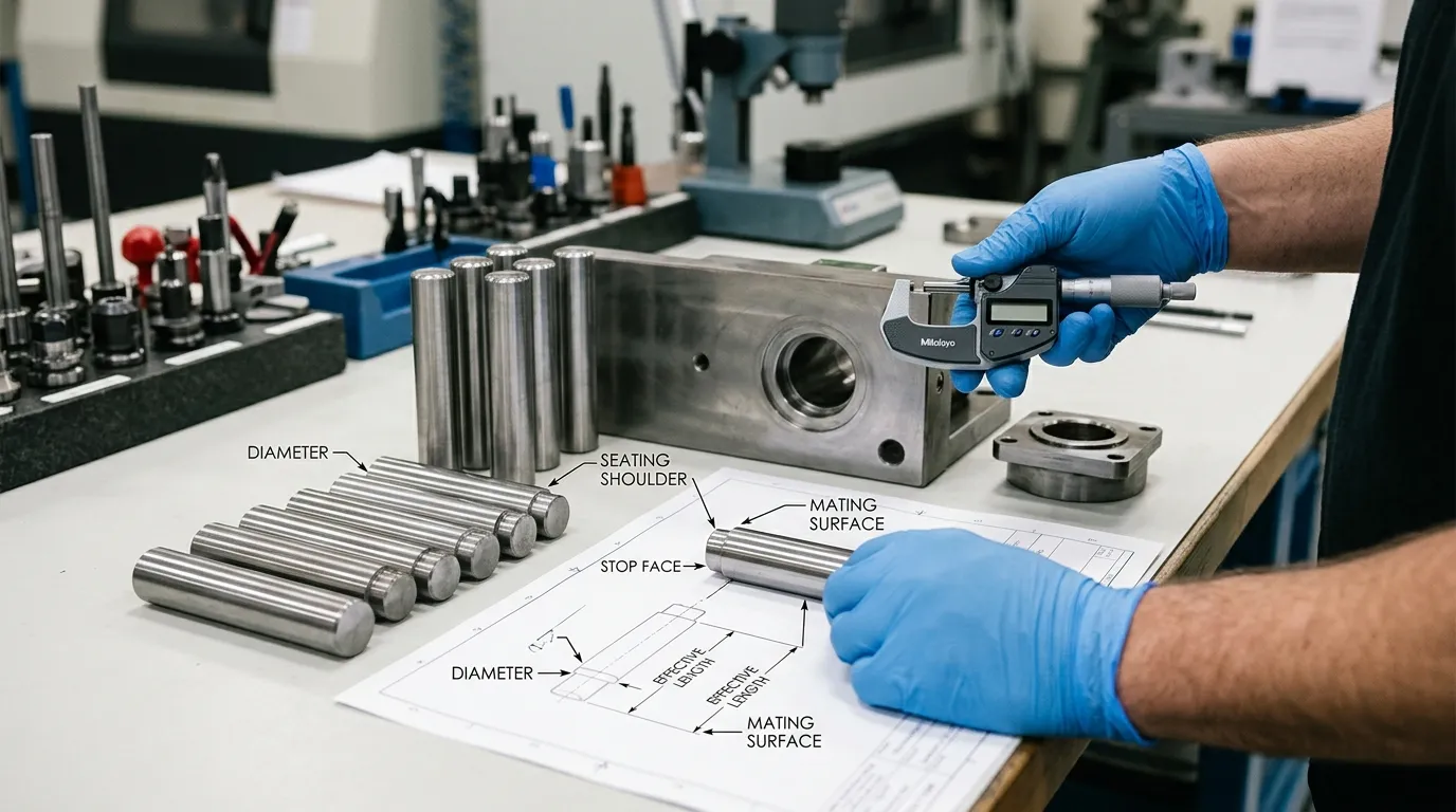
A useful RFQ should describe both the part and the mechanism in which it will operate. Sending only a nominal diameter and length leaves important engineering decisions undefined.
Informacje o zastosowaniu
Zawiera:
- type of moving mechanism;
- stopped component;
- direction of travel;
- total stroke;
- required final position;
- moving mass;
- expected contact velocity or impact condition;
- external hydraulic, spring, Maszyna, or mechanical force;
- number and spacing of stops;
- operating temperature and contamination conditions where relevant;
- applicable automotive customer or tooling specification.
Definicja składowych
Określ:
- Średnica sworzni;
- total length;
- effective stop length;
- unsupported or exposed length;
- Geometria końcowa;
- shoulder and seating dimensions;
- mounting-hole relationship;
- fit or retention requirement;
- removal feature if replacement is expected;
- geometric controls needed for seating or contact.
Wymagania materiałowe i procesowe
State:
- material grade and condition;
- heat-treatment requirement;
- target hardness where justified;
- functional surface requirements;
- mating-surface material and hardness;
- need for a wear plate or replaceable insert.
Inspekcja i dokumentacja
Depending on the project, request:
- dimensional inspection results;
- Weryfikacja twardości;
- Dokumentacja materiałowa;
- drawing revision control;
- part or batch identification;
- first-article or sample approval;
- confirmation of replacement interchangeability;
- customer-specific automotive records.
IATF 16949 concerns automotive quality-management systems. Certification may support process control, but it does not prove that a particular limit-pin geometry, Materiał, or load rating is correct for the mold.
SunshinePro states that it supports custom mold parts based on customer drawings and lists standard and non-standard mold limit pin options. Its published Mold Limit Pin configuration uses S45C, with stated diameter and length tolerances, 15–17 HRC hardness, precyzyjne szlifowanie, oraz obróbkę cieplną próżniową. These are product-page specifications, not universal design criteria for every automotive application.
The listed configuration should be checked against the actual mechanism load, Wsparcie, Powierzchnia łącząca, Dopasowanie, endpoint requirement, and customer specification. Readers who have completed these checks can review SunshinePro’s Opcje przypnień limitujących formę lub Złóż rysunek i wymagania aplikacyjne for quotation.
Udostępnij:



Napisane przez Sunshine
W Sunshine, Jesteśmy profesjonalnym producentem i dostawcą komponentów do precyzyjnych form, oferując szeroką gamę produktów do tłoczenia i formowania wtryskowego. Naszym głównym celem są formy do dziurkania, Sworznie wyrzutowe i tuleje, oraz słupy i tuleje. Dzięki zaawansowanej obróbki CNC, Ścisła kontrola jakości, oraz silne możliwości produkcyjne, Zapewniamy niezawodność, Części o wysokiej precyzji, wraz ze standardowymi komponentami dostępnymi na stanie, zapewniającymi szybkie i efektywne globalne dostawy.
WIADOMOŚCI
UZYSKAJ USŁUGĘ
Z wysokiej jakości częściami dostosowanymi do każdego budżetu oraz przyjaznym personelem przeszkolonym, by Twoja wizyta była poinformowana i bezproblemowa.
