



Sworzeń pozycjonujący formę a szpilec prowadzący: Porównanie ról w wyrównaniu
A guide pin and a mold positioning pin both help align mold components, but they normally control different stages of that alignment.
A guide pin travels through a matching guide bushing to control how the mold halves approach, close, and separate. A positioning pin, locator, or interlock usually acts nearer the closed position, where it establishes more exact final registry or helps resist lateral displacement.
The two components are therefore not automatically interchangeable. A conventional mold may rely mainly on guide pins and bushings, while a mold with demanding shut-offs, offset loading, or strict parting-line alignment may use a guide system together with secondary positioning components.
Terminology varies between manufacturers. Some catalogs use “locating pin” as another name for a guide pin, while others use it for a separate final-positioning device. The component’s geometry, mating interface, engagement sequence, and mechanical role matter more than its name. Broader information about guide fits, bushing wear, and maintenance is covered in Sworznie i tuleje formowe (wnioskowane).
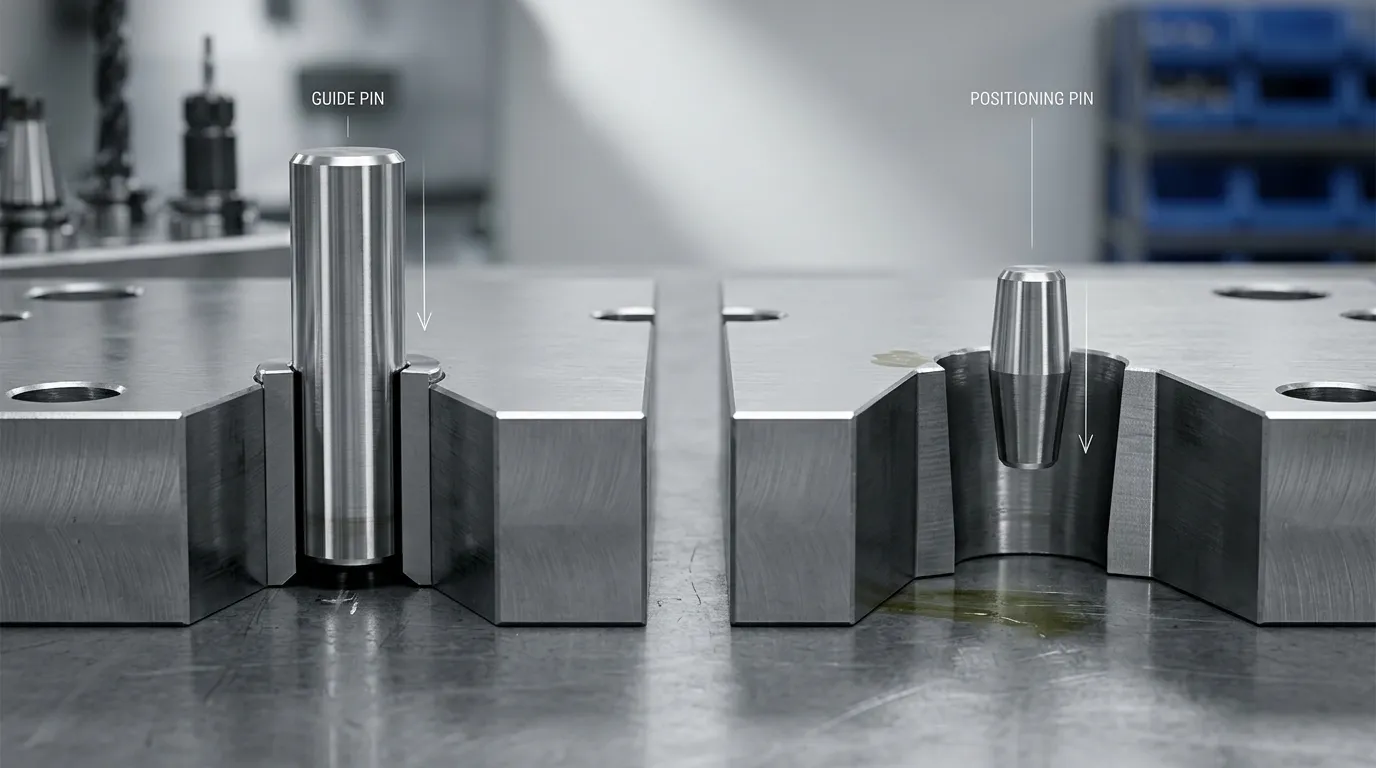
Guide Pin vs Positioning Pin: The Functional Difference
The clearest way to compare the two components is by the function they perform inside the mold.
| Punkt porównania | Sworzeń prowadzący | Pinezek pozycyjny lub lokalizator |
|---|---|---|
| Główna rola | Wskazuje względny ruch między połówkami formy | Ustala lub udoskonala ostateczną pozycję zamkniętą |
| Typowy ruch operacyjny | Przesuwa się przez tulejkę prowadzącą podczas otwierania i zamykania | Engages a receiver, locating bushing, socket, Zwężanie, or contact surface |
| Główny etap operacyjny | Zaczyna pracować podczas podejścia typu "forma połowa" | Często staje się najważniejszym w okolicach ostatecznego zamknięcia |
| Składnik parujący | Tulejka prowadząca lub tulejka prowadząca | Locating bushing, receiver, socket, alignment lock, or mating locating surface |
| Zasada dopasowania | Wymaga wystarczającego prześwitu do wielokrotnego przesuwania | May use closer, Stożkowa, or positive contact depending on the design |
| Wkład w wyrównanie | Podejście sterujące i ogólne nawigowanie połową formy | Kontroluje ostatnią rejestrację lub pozycję boczną |
| Rola bocznego załadunku | May experience side loading, but should not automatically be treated as the sole lateral-positioning system | Może być wybrany specjalnie w celu kontroli ruchu bocznego w pobliżu zamknięcia |
| Typowy wzorzec zużycia | Punktacja, irytujące, bushing wear, or increased clearance | Contact-face wear, Fretting, Peening, taper damage, or loss of final registry |
| Typowe zastosowanie systemu | Podstawowa część wielu systemów naprowadzania formy | Dodawane, gdy wymagania końcowego pozycjonowania przekraczają to, co powinien zapewnić sam system prowadzący |
A guide pin is commonly called a leader pin, guide post, lub filar prowadzący. It enters a guide bushing and keeps the core and cavity halves moving along the intended path. For deeper coverage of guide geometry, zużycie, oraz selekcja, Zobacz Sworznie prowadzące formę.
A positioning component works differently. Its purpose is not necessarily to guide the full mold stroke. It may engage only near closure, where the core half, cavity half, Wkładki, shut-offs, and parting surfaces must reach a repeatable relationship.
Dlaczego nazwy katalogów mogą być mylące
Component names are not fully standardized across mold-component catalogs.
“Guide pin” and “leader pin” are often used for the same sliding guide component. “Guide post” and “guide pillar” are also common regional or catalog terms.
“Locating pin” is less consistent. Depending on the supplier or drawing, it may refer to:
- Sworzeń prowadzący, który wchodzi do tulejki
- Statyczny kołek służący do lokalizowania złożonych płyt
- Stożkowy lub prosty element używany do końcowego pozycjonowania
- Sworzeń zazębiający osobny odbiornik lub tulejkę lokalizującą
- Część większego systemu blokady wyrównania lub blokady
A static dowel pin should not be confused with a component that operates throughout mold opening and closing. A dowel may establish the assembled position of two plates, while a guide pin moves repeatedly through a bushing during each cycle.
To identify the component correctly, examine:
- Czy przesuwa się przez tulejkę
- Gdy załącza się podczas zamykania formy
- Czy działa przez cały ruch
- Niezależnie od tego, czy jego głównym celem jest naprowadzanie ruchu, czy ostateczna lokalizacja
- Whether it has straight clearance, tapered contact, or positive locating surfaces
- Który ładuje rysunek, oczekuje jego oporu
Jak elementy prowadzące i pozycjonujące współdziałają podczas zamykania formy
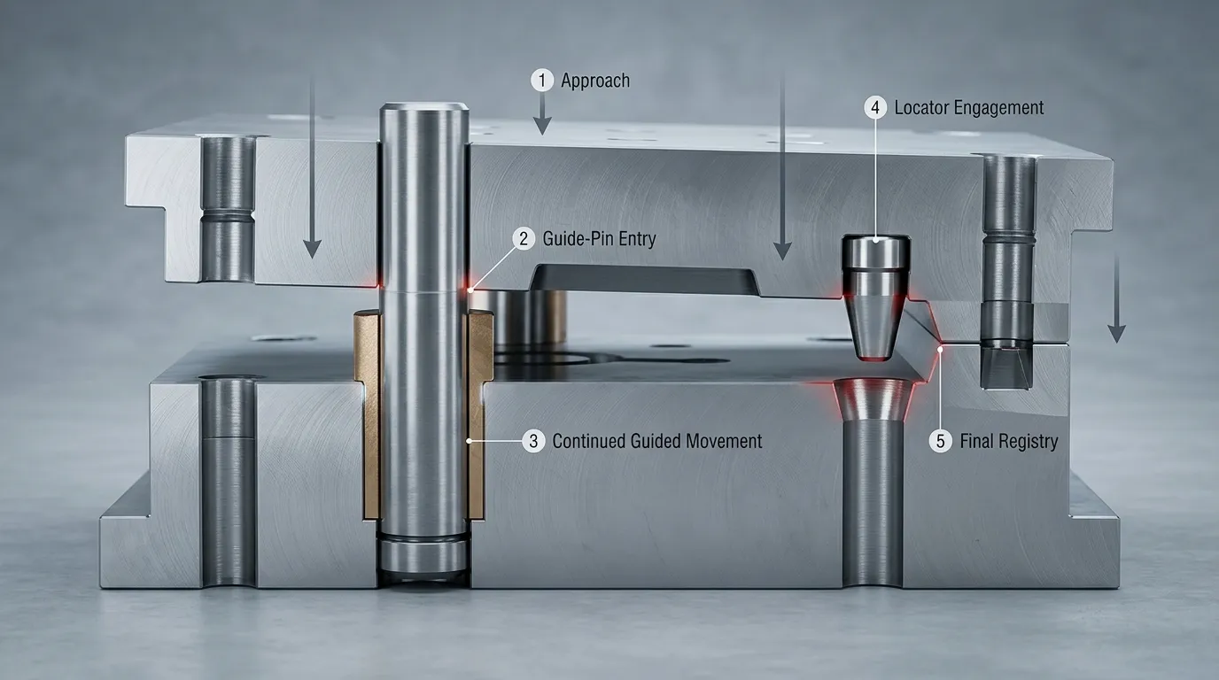
A combined guide and positioning system can be understood as a sequence rather than two components performing the same task.
- The mold halves begin to approach.
The lead-in portion of the guide pin moves toward the guide bushing. - The guide pin enters the bushing.
The pin-and-bushing relationship controls the relative movement of the core and cavity halves. The sliding interface helps prevent uncontrolled lateral movement during approach. - The mold approaches the closed position.
The guide system continues to control movement, but its operating clearance still allows repeated sliding. - The secondary positioning element engages.
Where the design includes a positioning pin, tapered locator, alignment lock, or mold interlock, that component begins controlling the final positional relationship. - Final registry is established.
The parting surfaces, shut-offs, Ubytki, Kolory, and related mold features reach their intended closed relationship before or during clamping.
During opening, this sequence reverses. The final-positioning surfaces disengage, and the guide pins continue controlling separation through the guide bushings.
This sequence is a functional example, not a universal timing rule. Actual engagement depends on the component geometry and mold drawing. In some designs, components described as “locating pins” may begin engaging earlier than expected because they also perform a guiding function.
Can a Positioning Pin Replace a Guide Pin?
Usually, a final-positioning component should not be assumed to replace the full-stroke guidance provided by guide pins and bushings. It may not have the length, sliding interface, or engagement range needed to control the mold throughout opening and closing.
The reverse is also true. A guide pin should not automatically be expected to provide every final-positioning function. Its sliding clearance, Stan zużycia, span, and exposure to lateral forces may limit how accurately it controls the final relationship between critical mold features.
Właściwe rozwiązanie zależy od zastosowania.
| Stan pleśni | Podejście do prawdopodobnego wyrównania |
| Forma konwencjonalna o umiarkowanych wymaganiach do ustawienia i ograniczonym obciążeniu bocznym | Sworznie prowadzące i tuleje mogą być wystarczające |
| Forma z nieregularną geometrią rozdzielania lub wymagające odcinanie | System prowadzenia oraz pozycjonowanie wtórne mogą być odpowiednie |
| Duże lub ciężkie połowy formy | Może być wymagane dodatkowe wsparcie lokalizacyjne lub blokujące |
| Offset cores, asymmetric forces, lub boczny ładunek | Komponenty końcowego pozycjonowania mogą pomóc w kontroli rejestru bocznego |
| Krytyczne ostateczne wyrównanie cech formy | System prowadzenia i dedykowane komponenty pozycjonowania mogą współpracować |
| Istniejące problemy z wiązaniem lub ruchem | Inspect guide pins, tulejki, mounting alignment, Zanieczyszczenie, i noszenie |
| Istniejące niedopasowanie linii rozdzielczej mimo akceptowalnego ruchu prowadnicy | Sprawdź powierzchnie końcowego pozycjonowania i lokalizacji oraz system prowadzący |
Kiedy prowadnice mogą być wystarczające
Guide pins and bushings may provide enough alignment when:
- Forma ma konwencjonalną geometrię rozdzielania
- Siły boczne i asymetryczne są ograniczone
- Wymagania dotyczące wyrównania są umiarkowane
- Rozpiętość prowadząca i układ elementów są odpowiednie
- Sworznie i tuleje pozostają prawidłowo zamontowane i w akceptowalnym zużyciu
- Nie ma powtarzających się dowodów na utratę w ostatecznym rejestrze
- System przewodnika został wybrany zgodnie z rzeczywistym rozmiarem formy i warunkami pracy
This does not mean that guide pins are imprecise. It means that their main job is controlled movement through a sliding interface. The required running clearance and accumulated wear must be considered when deciding whether they can also satisfy the mold’s final-positioning requirements.
Kiedy pozycjonowanie drugorzędne jest bardziej odpowiednie
A separate positioning system becomes more relevant when the mold has:
- Głębokie ubytki lub wymagające, zamknięte relacje
- Duże lub ciężkie ruchome połówki formy
- Irregular, krok, or non-flat parting surfaces
- Obciążenia przesunięcia lub asymetryczne układy wnęk
- Działania boczne powodujące znaczące siły boczne
- Critical insert, Rdzeń, or cavity registry requirements
- Powtarzające się niedopasowanie linii rozdzielania, które nie jest spowodowane wyłącznie zużytymi tulejami prowadniczymi
- Temperatury robocze, które istotnie wpływają na prześwit lub relacje kontaktowe
Secondary positioning does not have to mean one specific pin design. The function may be performed by a straight locator, tapered locator, alignment lock, side lock, or mold interlock.
Straight and tapered positioning geometries create different engagement and contact conditions. That choice should be evaluated separately rather than treated as part of the basic guide-pin comparison.
Oba systemy powinny współpracować
Many demanding molds separate the two alignment functions:
- Guide pins and bushings control approach, closing movement, and opening movement.
- Positioning pins, locators, or interlocks refine the final closed position.
This division allows each interface to perform the task it was designed for. The guide components do not have to act as rigid final locks, while the positioning components do not have to guide the mold through its full travel.
The systems still have to be coordinated. If the guide arrangement permits the mold halves to reach a position that conflicts with the locator geometry, the positioning components may strike, bind, or wear unevenly. Mounting accuracy, engagement order, Warunki termiczne, and the relationship between male and female components must therefore be considered together.
How Fit, Side Load, and Temperature Change the Selection
Fit is one of the main reasons a guide pin and positioning component cannot be evaluated in the same way.
A guide pin must move repeatedly through its bushing. The interface needs operating clearance that accounts for component tolerances, Smarowanie, Zanieczyszczenie, Temperatura, mounting alignment, i noszenie. Too little functional clearance can cause binding or galling. Too much clearance can reduce alignment repeatability.
A positioning component may use a different contact principle. A tapered locator or interlock can approach a more positive final relationship as the mold closes. A straight positioning pin may use a controlled fit with a matching receiver. The correct choice depends on how much movement must be allowed before engagement and what load the interface must carry.
Side load also changes the decision. If lateral force acts on the mold halves, guide pins may be pushed against one side of their bushings. Repeated loading can produce uneven wear, increased clearance, lub wiążące. A dedicated positioning system can be used to control the final lateral relationship rather than leaving that entire function to the guide components.
Temperature must be included in the evaluation. Płyty formowe, Piny, tulejki, and locating components expand as temperature changes. That expansion can alter sliding clearance or increase contact at locating surfaces. A fit that works during room-temperature assembly may behave differently under operating conditions.
Standardized limits-and-fits terminology, such as the system defined in ISO 286-1, can reduce drawing ambiguity. It does not establish one universal guide-pin or positioning-pin fit. The designer still has to select the tolerance relationship for the actual material, Temperatura, Smarowanie, ładunek, Geometria, and component function.
Wear and Failure Clues: Which Alignment Function Is Being Lost?
The wear pattern often indicates whether the problem is mainly related to movement guidance or final positioning.
| Obserwowany stan | Bardziej prawdopodobne jest miejsce do inspekcji | Dlaczego |
| Oprawy podczas otwierania lub zamykania | Sworznie prowadzące, Tuleje prowadzące, mounting alignment, Zanieczyszczenie | Przesuwna ścieżka prowadząca może być ograniczona lub niewyrównana |
| Długie znaki punktacji na przypięciu | Interfejs przewodnika | Kontakt ślizgowy, Zanieczyszczenie, Niewystarczające smarowanie, or side loading may be present |
| Galling lub transfer materiału | Para sworzni prowadzącej i tuleja | Zużycie adhezyjne może pojawić się podczas kontaktu z powierzchniami ślizgowymi w nieodpowiednich warunkach |
| Nierówne zużycie tulei | System prowadzący i wyrównanie formy | Obciążenie boczne lub błąd montażu może wymuszać kontakt z jedną stroną |
| Zwiększona swoboda przepływu przed zamknięciem | Prześwitanie przewodników | Zużycie mogło pogłębić relację między pinami a tulejkami |
| Progi lub polerowane łaty kontaktowe na powierzchniach lokalizatorów | System pozycjonowania | Powtarzający się kontakt lub mikroruch wpływa na powierzchnie końcowe |
| Uwieranie lub uszkodzone krawędzie na lokalizatorze | Sekwencja zaangażowania lub niewyrównanie | Elementy mogą uderzać zanim zostaną prawidłowo wyrównane |
| Uszkodzony stożek lub nierówny kontakt stożkowy | Komponent pozycjonowania | Końcowy kontakt lokalizujący może już nie być prawidłowo rozprowadzony |
| Niedopasowanie linii rozdzielczej lub niespójność przy wyłączaniu | Kompletny system wyrównania | Loss of final registry may involve locators, Zużycie przewodnika, Ruch płyty, or other mold conditions |
No single symptom proves that one component has failed. Flash, Niedopasowanie, or binding can have several causes. Inspection should include both male and female components, their mounting features, the mold plates, Warunki smarowania, Zanieczyszczenie, and evidence of lateral loading.
Replacing only a worn pin may not restore the original relationship if the mating bushing or receiver is also damaged. The complete interface should be evaluated.
Lista kontrolna wyboru rysunków i zapytań o zapytania od dostawców
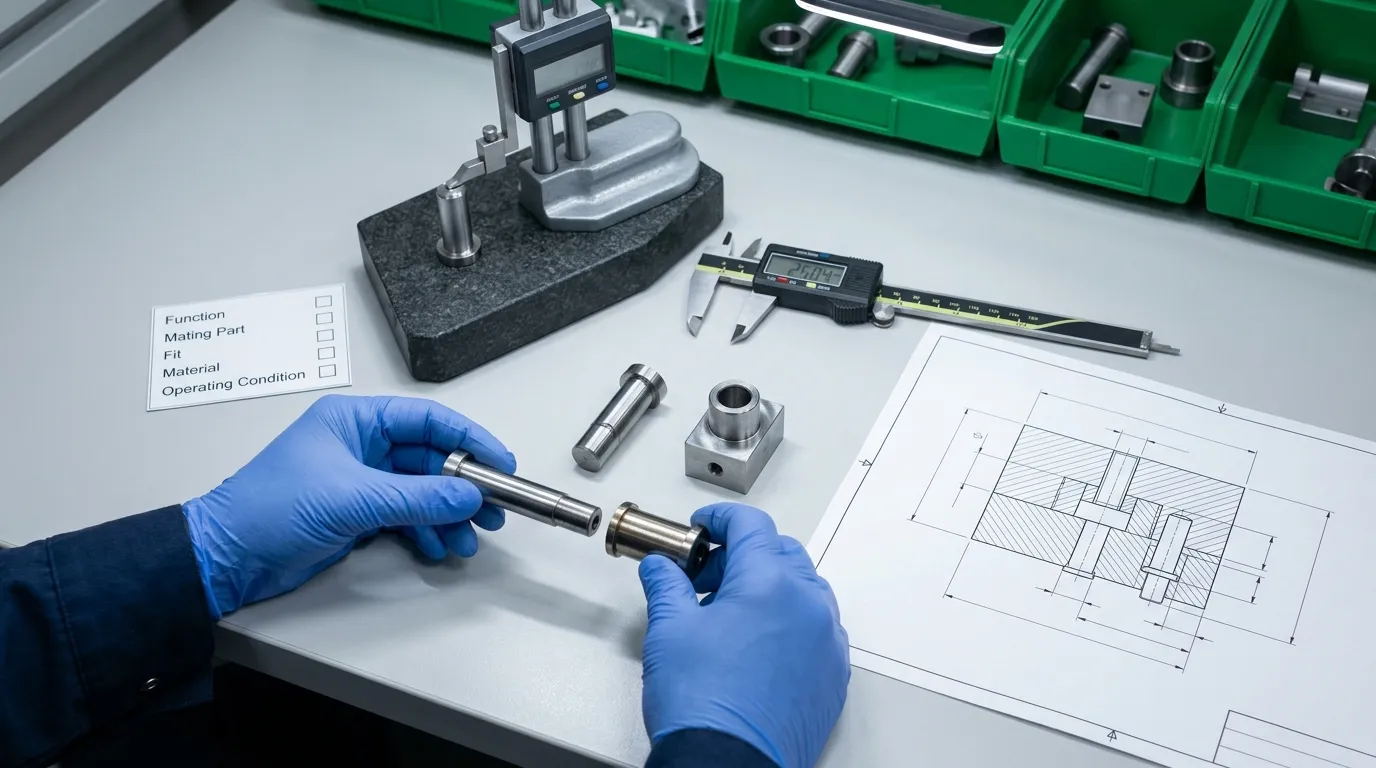
A supplier cannot reliably determine the correct component from the words “guide pin” or “positioning pin” alone. The RFQ should define the required function and the mating relationship.
Include the following information:
- Funkcja wymagana: State whether the component provides full-stroke guidance, final registry, lateral positioning, static plate location, or a combined role.
- Assembly drawing: Provide a mold section showing where the pin, tuleja, receiver, or locating surface is installed.
- Mating components: Identify both sides of the interface rather than specifying only the pin.
- Nominal dimensions: Include diameters, Długości, Ramiona, Zwężanie, engagement depths, and mounting dimensions.
- Tolerancje wymiarowe: Identify the tolerance for each critical feature and make clear which diameter or surface it applies to.
- Geometric tolerances: Add straightness, Koncentryczność, prostopadłość, or position controls where the design requires them.
- Material and heat treatment: Specify these only according to the approved design or service conditions.
- Hardness and surface finish: State the required features instead of assuming one universal value for all guide or positioning parts.
- Powłoka lub obróbka powierzchni: Include it only when required and define the treated surfaces.
- Operating temperature: Describe the expected thermal condition where it may affect clearance or locating contact.
- Lubrication and contamination conditions: Indicate whether the component operates with lubrication and whether dust, resin residue, or other contamination is expected.
- Kierunek obciążenia: Identify unusual lateral, offset, or asymmetric loading.
- Installation method: Define press-fit, Zachowanie, Na ramieniu, Kołnierza, or other mounting requirements.
- Replacement access: Show how the component will be removed and whether the mating part is replaceable.
- Wymagania inspekcyjne: Request dimensional reports or other records where critical features require verification.
The sourcing route also matters. A catalog component may be appropriate when the required geometry, Dopasowanie, Materiał, and mounting method match an established standard. A drawing-based component may be needed when the mold has unusual engagement geometry, nonstandard dimensions, special mating surfaces, or application-specific material requirements.
SunshinePro publishes guide posts, tulejki, locating-related accessories, i inne Standardowe części formy. The company also states that custom mold and die accessories can be produced from drawings or samples. Those broad capabilities do not replace the need for a complete technical specification.
Wybór odpowiedniego systemu wyrównania formy
There is no universal winner in the mold positioning pin vs guide pin comparison.
Use guide pins and bushings when the mold needs controlled relative movement during opening and closing. Use a positioning component when the design requires more definite final registry, better control of lateral displacement, or repeatable contact near the closed position. Use both when movement guidance and final positioning are separate requirements.
The final decision should come from the mold drawing, parting geometry, expected loads, Temperatura pracy, allowable clearance, mating-component design, and maintenance access—not the catalog name alone.
For a standard-part or drawing-based component review, prepare the mold section, required function, mating geometry, Wymiary, Tolerancje, Wymagania materialne, and operating conditions before kontaktowanie się z SunshinePro.
Udostępnij:



Napisane przez Sunshine
W Sunshine, Jesteśmy profesjonalnym producentem i dostawcą komponentów do precyzyjnych form, oferując szeroką gamę produktów do tłoczenia i formowania wtryskowego. Naszym głównym celem są formy do dziurkania, Sworznie wyrzutowe i tuleje, oraz słupy i tuleje. Dzięki zaawansowanej obróbki CNC, Ścisła kontrola jakości, oraz silne możliwości produkcyjne, Zapewniamy niezawodność, Części o wysokiej precyzji, wraz ze standardowymi komponentami dostępnymi na stanie, zapewniającymi szybkie i efektywne globalne dostawy.
WIADOMOŚCI
UZYSKAJ USŁUGĘ
Z wysokiej jakości częściami dostosowanymi do każdego budżetu oraz przyjaznym personelem przeszkolonym, by Twoja wizyta była poinformowana i bezproblemowa.
