


Mold Limit Pin Installation Guide: Seating, Retention, and Access
A mold limit pin must do more than fit inside its mounting hole. It must seat against the correct reference surface, project to the drawing-defined height, remain securely retained, and still be accessible when inspection or replacement is needed.
Limit pins belong to the wider group of mold standard parts (inferred), but catalog dimensions alone do not determine whether a pin can be installed correctly. The mold assembly drawing, component drawing, bill of materials, mounting-bore condition, and retention design must agree before installation begins.
This guide covers mechanical limit or stop pins that establish a plate-travel, contact, or impact-control position. It does not provide universal fit, torque, insertion-force, seat-depth, or hardness values. Those requirements must come from the approved mold documentation.
Confirm the Pin’s Function Before Installation
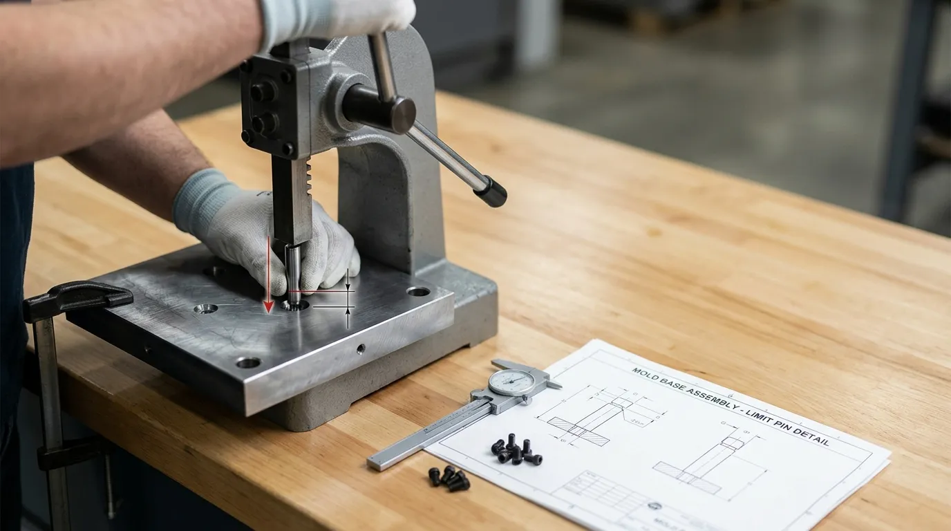
The first step is not pressing the pin into the plate. It is confirming what the component is expected to do.
Terms such as limit pin, stop pin, guide pin, dowel pin, return pin, and ejector pin are sometimes used inconsistently. Two pins may look similar while performing different functions inside the mold.
Distinguish Limit Pins from Guide, Dowel, Return, and Ejector Pins
| Składnik | Główna funkcja | Typical relationship | Main installation concern |
|---|---|---|---|
| Limit or stop pin | Establishes a travel, contact, or impact-control position | Contacts or limits the movement of a plate or mechanism | Installed projection, seating, retention, and contact height |
| Guide or leader pin | Aligns moving and stationary mold sections | Runs through a mating guide bushing | Alignment, fit with the bushing, lubrication, and wear |
| Dowel or locating pin | Locates components relative to one another | Fits between plates or parts that must maintain position | Positional accuracy and resistance to relative movement |
| Return pin | Helps return an ejector-related mechanism | Works with the ejector assembly during mold closing | Travel, interference, and return timing |
| Sworzeń wyrzutnika | Pushes the molded part from the cavity or core | Moves through the ejector system and molding area | Length, clearance, motion, and contact with the molded part |
Do not assume that a pin is a limit pin because of its shape or location. Check the assembly drawing and BOM designation. The drawing should show which plate carries the pin, which surface contacts it, and what movement the pin is intended to control.
If the component is part of the mold’s alignment system, refer to the separate guide on Sworznie i tuleje formowe rather than applying stop-pin installation logic.
Read the Drawing and BOM as the Controlling Instructions
Before removing an old pin or fitting a replacement, verify:
- Current drawing revision
- Component part number
- Quantity and location
- Installation direction
- Body diameter and overall length
- Shoulder, head, flange, or threaded features
- Hole or shaft fit callout
- Mounting-hole depth
- Reference seating surface
- Required installed projection
- Retention method
- Fastener access
- Extraction or removal method
The International Organization for Standardization’s ISO 286 system provides recognized terminology for hole and shaft tolerances. It does not tell the installer which fit is correct for a specific limit pin. The approved drawing must make that decision.
Stop the work if the drawing, BOM, and actual component conflict. Additional force will not correct an incorrect part number, obsolete revision, or mismatched geometry.
Prepare the Mold, Pin, and Mounting Feature
Preparation determines whether the pin reaches its intended seat without damaging the bore or plate.
The mold must be safely supported, the component must match the documentation, and the mounting feature must be clean and dimensionally suitable before insertion starts.
Isolate and Support the Mold Safely
A mold may contain electrical, hydraulic, pneumatic, mechanical, gravitational, or spring-loaded energy. Control those hazards under the approved workplace procedure before disassembly or installation.
The general principle is consistent with OSHA’s requirements for the control of hazardous energy, although the exact legal and procedural requirements depend on the country, machine, and workplace.
Before working on the pin:
- Isolate the molding machine and connected systems.
- Release or restrain stored energy.
- Support plates that could shift after a component is removed.
- Position the mold so installation force can be applied in line with the pin axis.
- Confirm that no person is exposed to an unsupported moving plate or ejector assembly.
This is not a substitute for local lockout, maintenance, or lifting procedures.
Inspect the Replacement Pin
Compare the replacement pin with the latest component drawing rather than relying only on the old pin.
Check:
- Średnica nadwozia
- Całkowita długość
- Shoulder or head dimensions
- Contact-face condition
- Thread size and thread damage
- Chamfers and edge condition
- Surface scoring or corrosion
- Straightness and visible deformation
- Part number or traceable identification
SunshinePro’s listed Mold Limit Pin product includes product-specific material, tolerance, hardness, threaded-feature, and customization information. Those figures apply only to the listed product configuration. They must not replace the project drawing or be treated as universal installation values.
Questions involving wider material, tolerance, finish, or incoming-QC requirements belong under the broader topic of Części do precyzyjnych form.
Inspect the Bore, Counterbore, and Seating Face
A correct pin can still install incorrectly when the receiving feature is damaged or contaminated.
Inspect the mounting area for:
- Chips, grease deposits, hardened residue, or corrosion
- Burrs around the hole entrance
- Raised metal around a counterbore
- Scoring or material transfer inside the bore
- Distortion or ovality
- Cracked or damaged seating surfaces
- Incorrect hole depth
- Unapproved rework
- Damage from previous removal attempts
Remove contamination using an approved cleaning method, but do not enlarge, polish, grind, or reshape the bore simply to make the replacement fit.
Manufacturer assembly documentation commonly requires installers to check counterbores, remove burrs, inspect seating surfaces, and confirm component height before final assembly. The same control principle applies here: clean geometry must be verified before force is applied.
Establish the Correct Seat and Installed Projection
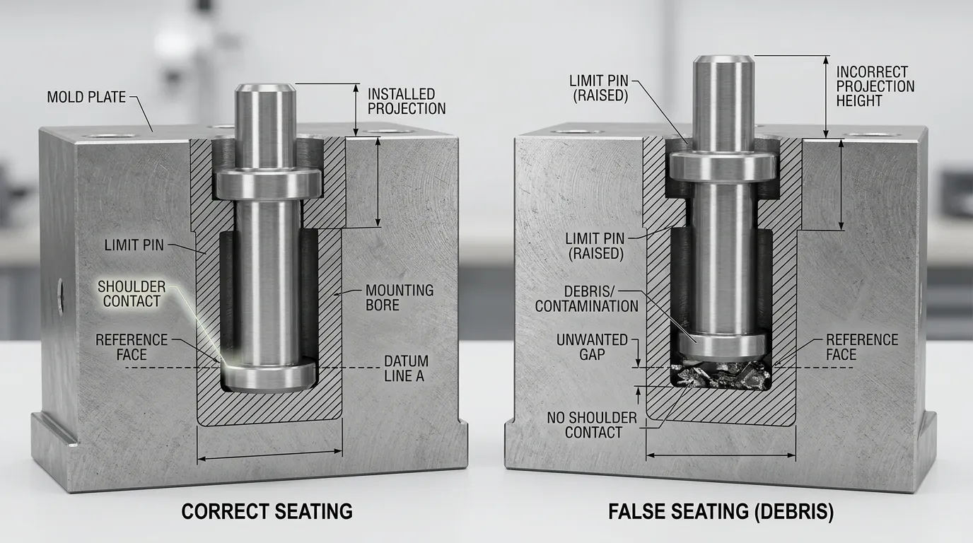
A pin is not acceptable merely because it appears fully inserted.
Its axial position must be established by the intended reference face. Depending on the design, that may be a shoulder, head, flange, counterbore, retainer, or another drawing-defined surface.
Identify the Reference Face and Measurement Datum
The drawing should answer two separate questions:
- Where does the pin stop during installation?
- From which mold surface is its exposed height measured?
These surfaces are not always the same.
For example, a shoulder may seat inside a counterbore while the installed projection is measured from the outer plate face. A threaded or retained design may establish axial position through a head or clamping component rather than through the bottom of the hole.
Use one controlled datum for all measurements. Record that datum with the measured projection so another technician can repeat the inspection later.
A vague instruction such as “press until fully seated” is inadequate unless the seating surface and final height are defined.
Prevent False Seating in Blind Holes
Blind holes require special attention because the pin can contact the hole bottom before its intended shoulder or reference surface reaches the seat.
False seating may result from:
- Insufficient hole depth
- Chips or debris at the bottom
- A burr beneath the shoulder
- Trapped residue or damaged metal
- An incorrect pin length
- A mismatched head or shoulder geometry
- Previous unapproved bore modification
Common warning signs include:
- Excessive installed projection
- A visible gap beneath the shoulder
- Unexpectedly high insertion resistance
- A pin that appears tilted
- Different installed heights among nominally identical pins
Do not apply additional force when these symptoms appear. Remove the pin using the approved method, inspect the hole and component, and compare both with the drawing.
Check Common Height When Several Pins Share Contact
Several limit pins may form one contact plane. Equal pin lengths do not guarantee equal installed heights because bore depth, seat condition, debris, plate distortion, and component geometry can vary.
When multiple pins are intended to contact together:
- Measure every pin from the same datum.
- Compare actual installed projections.
- Check the mating plate for rocking.
- Look for one pin contacting before the others.
- Inspect contact surfaces for uneven marking.
- Confirm that no pin is carrying contact because another pin is seated too low.
The drawing or approved engineering specification must provide the allowable variation. Do not invent an acceptance tolerance from a different mold or catalog.
Install the Pin with Controlled Axial Support
Once the component and mounting feature have been verified, install the pin in the direction specified by the drawing.
- Confirm the required fit and installation direction.
- Support the plate close to the mounting area.
- Align the pin axis with the bore axis.
- Place installation tooling against an approved non-functional surface.
- Apply controlled axial force.
- Monitor the pin for tilt, scoring, shaving, or abnormal resistance.
- Stop when the drawing-defined seating condition is reached.
- Measure the installed projection rather than accepting insertion force as proof of completion.
- Inspect the surrounding plate and exposed pin surfaces for damage.
For an interference-fit arrangement, the fit class influences the required assembly force and future removability. That does not justify estimating the force by feel or copying a fit from another component.
Avoid uncontrolled hammer impact. Side loading can cock the pin, damage the hole entrance, deform the plate, or mark the functional contact face.
Heating, cooling, surface modification, or lubrication should be used only when the approved installation procedure permits it and defines the applicable conditions.
Stop When the Pin Does Not Install Cleanly
Stop the operation if you observe:
- Sudden or inconsistent resistance
- Pin tilt
- Metal shaving
- Bore scoring
- Plate distortion
- A damaged contact face
- Excessive projection
- A shoulder that does not reach its seat
- A fit that is unexpectedly loose
Recheck the part number, fit callout, bore diameter, hole depth, seat geometry, and component condition. A forced installation can conceal the original mismatch while creating a second problem in the plate.
Match Retention Security with Future Service Access
The pin’s fit and its axial retention are related but not always identical.
Some designs depend mainly on interference. Others use screws, threads, blocks, plates, or trapped heads. The correct choice is the one shown in the approved design, not the method that is easiest to apply during maintenance.
Compare Retention Methods by Security and Serviceability
| Retention method | Main characteristic | Service-access consideration | Main risk to check |
| Interference fit | Radial fit provides retention | Removal may require rear access, pulling equipment, or plate disassembly | Bore damage or loss of retention after repeated removal |
| Threaded pin or retaining screw | Mechanical fastener controls axial movement | Fastener must remain accessible after assembly | Incorrect torque, damaged threads, or inaccessible fastener |
| Screw-clamped design | A separate screw or clamp secures the pin | Can be serviceable if the clamp is exposed | Clamp movement or insufficient access |
| Retainer plate or block | A plate or block traps the pin | May allow controlled removal but adds fasteners and machining | Retainer installed in the wrong sequence |
| Trapped head or shoulder | Adjacent plates capture the component | Often requires plate separation for removal | Future maintenance may be difficult |
| Retaining compound | Adhesive supports a cylindrical joint | Removal and cure conditions must be planned | Incorrect gap, contamination, temperature, or unapproved use |
Retaining compounds are not a general cure for a loose or damaged bore. Products such as LOCTITE 638 have defined gap, preparation, cure, temperature, and material requirements. Use one only when the component design and engineering instructions approve it.
Confirm Front, Rear, and Extraction Access
Before final assembly, confirm how the pin will be inspected and removed later.
Check whether:
- A retaining screw can be reached from the front
- A rear-access fastener becomes blocked by another plate
- A puller thread remains exposed
- A through-hole allows controlled support or removal
- A blind-hole pin has a defined extraction method
- A retainer plate can be removed without dismantling unrelated systems
- The pin’s orientation leaves access to flats, threads, or fasteners
- Future removal would place force against a sensitive plate surface
A retention method can be mechanically secure and still be a poor maintenance design. Record any plate separation or special tooling required for removal.
Measure and Validate the Installation
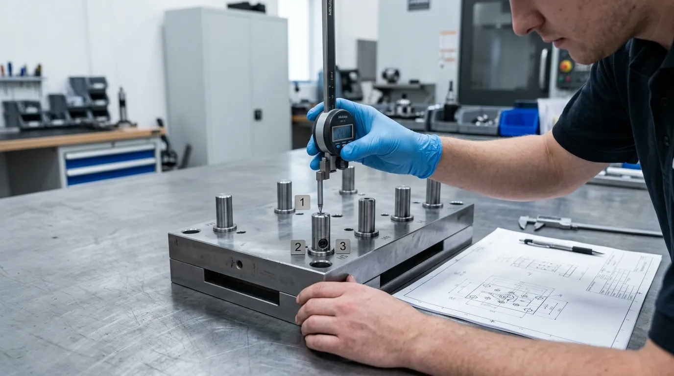
Installation is complete only after dimensional and functional checks confirm that the pin is seated, retained, accessible, and operating as intended.
Use the approved inspection equipment and the same datum established before installation.
- Measure the installed projection.
- Confirm the pin’s orientation.
- Verify the retention feature.
- Check screw or retainer access.
- Compare the heights of all pins that share contact.
- Check the mating plate for rocking or premature contact.
- Confirm clearance from nearby components.
- Perform an approved test fit or controlled dry cycle.
- Record the result.
Manufacturer assembly manuals from Mold-Masters illustrate the broader importance of drawing review, seating checks, installed-height measurement, clearance verification, and controlled test fitting. The exact acceptance values for a limit pin still come from its own mold documentation.
Record Installed Height, Retention, and Access
The installation record should identify:
- Mold or tool number
- Drawing revision
- Pin part number
- Measurement datum
- Actual installed projection
- Retention method
- Fastener status
- Front or rear access direction
- Extraction method
- Date and inspector
- Approved deviations, if any
Photographs of the installed pin, seat, and access arrangement may also help future maintenance teams understand the accepted condition.
Use a Controlled Test Fit or Dry Cycle
Follow the approved machine and mold procedure for any movement test.
Observe:
- Contact sequence
- Plate travel
- Unusual resistance
- Rocking
- Zakłócenia
- Fastener movement
- Uneven pin contact
- A mechanism stopping before or after the intended position
Stop the test if the mold does not move or contact as the drawing intends. Do not proceed directly to full-speed production to see whether the problem resolves itself.
Troubleshoot Common Limit-Pin Installation Problems
| Objawy | Likely causes | Wymagana odpowiedź |
| Pin stands too high | Burrs, debris, insufficient blind-hole depth, wrong pin length, wrong shoulder geometry, false bottoming | Remove using the approved method, inspect the seat and hole depth, and compare the part with the drawing |
| Pin sits too low | Incorrect seat depth, damaged reference face, wrong component, unapproved material removal | Stop and obtain engineering review; do not shim or modify the pin without approval |
| Pin is tilted | Cocked insertion, damaged bore, side loading, distorted plate, incorrect fit | Remove and inspect the bore and pin; check axial support and alignment |
| Pin is loose | Worn or oversized bore, wrong diameter, missing retention, incorrect fit | Do not rely on additional force or adhesive; assess bore repair, redesign, or replacement |
| One pin contacts first | Unequal projection, debris under another pin, mating-surface variation, incorrect component length | Measure every pin from one datum and inspect the contact plane |
| Retainer cannot be reached | Incorrect orientation, blocked fastener, poor assembly sequence, insufficient access planning | Correct before final assembly; document any required plate removal |
| Pin repeatedly loosens | Incorrect retention, damaged bore, changing load path, unsuitable geometry | Escalate for design and engineering review |
Installation should stop when:
- The drawing is unavailable or contradictory.
- The replacement component cannot be positively identified.
- The bore is cracked, enlarged, distorted, or heavily damaged.
- The seat no longer provides a stable reference.
- The required projection cannot be achieved.
- The specified retention cannot be installed or accessed.
- Several pins cannot be brought to the intended contact condition.
- The mold movement does not match the drawing after installation.
Do not use generic drilling, grinding, welding, peening, bonding, or oversizing methods as an automatic repair. Each can change the plate geometry, component fit, serviceability, or contact position.
Decide When the Pin or Mounting Feature Requires Replacement or Redesign
A standard replacement may be suitable when the current drawing remains valid and the bore, seat, fit, retention, and access arrangement are undamaged.
Engineering or supplier review is appropriate when:
- The existing bore is worn or oversized.
- The reference seat is damaged.
- The original drawing does not match the mold.
- A discontinued or altered pin geometry is present.
- The retention method cannot be serviced.
- Required projection cannot be achieved from the existing seat.
- The pin repeatedly loosens.
- Several pins do not share contact correctly.
- A standard component does not match the existing arrangement.
For a replacement review, prepare:
- Current pin drawing
- Mold assembly drawing
- Pin dimensions and geometry
- Mating-hole diameter and depth
- Required installed projection
- Material and heat-treatment requirement
- Retention method
- Access and extraction constraints
- Photographs or a physical sample where appropriate
SunshinePro states that it supplies a dedicated Mold Limit Pin product and can discuss custom mold accessories from drawings or samples. The exact material, tolerance, geometry, retention feature, and production feasibility still require project-specific confirmation.
Mold Limit Pin Installation Checklist
Before accepting the installation, confirm that:
- The component’s actual function has been identified.
- The current drawing and BOM revision have been checked.
- The mold and machine have been safely isolated.
- The pin dimensions and condition match the documentation.
- The mounting bore, counterbore, and seating face are clean and undamaged.
- The correct reference face and measurement datum are known.
- Blind-hole depth and bottom clearance have been checked where applicable.
- The pin was installed with controlled axial support.
- No scoring, shaving, tilt, or plate distortion is present.
- The specified retention method has been completed.
- Fastener and extraction access remain available.
- Installed projection has been measured.
- Multiple-pin contact has been checked where required.
- A controlled test fit or dry cycle has been completed.
- Actual measurements and observations have been recorded.
If the pin, bore, seat, or retention arrangement does not match the approved documentation, do not force the installation. Send the component drawing, mating-hole dimensions, required projection, and access details through the Strona kontaktowa SunshinePro for a project-specific review.
Udostępnij:


Scenariusz: Tonmoy
WIADOMOŚCI
UZYSKAJ USŁUGĘ
Z wysokiej jakości częściami dostosowanymi do każdego budżetu oraz przyjaznym personelem przeszkolonym, by Twoja wizyta była poinformacyjna i bezproblemowa.
