



Mold Limit Pin Tolerance and Fit for Repeatable Stopping
Mold limit pin tolerance and fit must control two different functions. The pin-to-bore fit controls retention, assembly force, Lokalizacja, and removability. The pin’s working height, Geometria siedzeń, surrounding plate dimensions, and contact faces control where the assembly actually stops.
A tight pin diameter alone does not guarantee repeatable stopping. Studnia matingowa, Głębokość miejsc, shoulder thickness, stop-face geometry, and complete axial tolerance stack must also be defined. Within the wider system of Standardowe części formy (wnioskowane), this makes the limit pin a component that must be specified from its installed function rather than from catalogue dimensions alone.
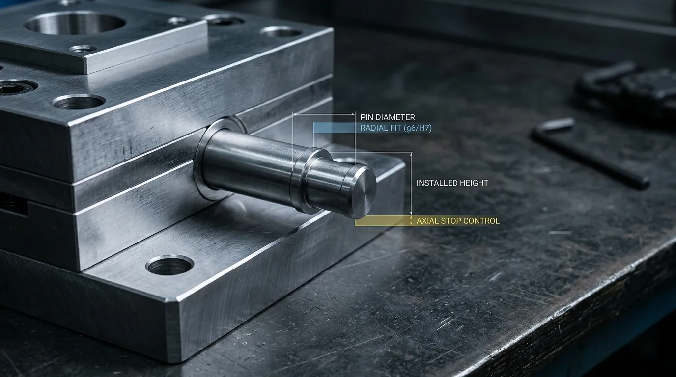
Jakie tolerancje i dopasowanie faktycznie kontrolują w sworzniu limitującym formę
The mounting fit and the stopping dimension solve different engineering problems.
Radial fit between the pin body and bore controls:
- Jak łatwo można złożyć sworzelkę
- Czy może się poruszać lub kołysać wewnątrz otworu
- Ile siły jest potrzebne do montażu
- Czy tylko tarcie ją utrzymuje,
- Jak łatwo można go usunąć podczas konserwacji
- Czy nadmierne zakłócenia mogą uszkodzić sworzeń lub płytę
Axial dimensions and contact geometry control:
- Wysokość robocza zainstalowana
- Ostateczna pozycja hamowania
- Czy kilka pinów styka się jednocześnie
- Jak rozkłada się obciążenie kontaktowe
- Czy fronta zatrzymania leży dokładnie przy przeciwnej nawierzchni
This distinction matters because a pin can be firmly retained while still producing an incorrect stop position. The opposite is also possible: the working height may be correct, but an excessively loose mounting fit can allow movement, Fretting, or inconsistent contact.
Limit Pin, Stop Pin, Guide Pin, or Dowel—Why the Name Matters
Dostawcy mogą używać takich określeń jak mold limit pin, Sworzeń zatrzymujący formę, stopper pin, Przycisk stop, lub Przycisk odpoczynku for related stopping components. The name alone does not confirm the exact geometry or installed function.
A guide pin normally works with a bushing to control sliding alignment between mold sections. A dowel pin locates stationary components relative to each other. A return pin and an ejector pin perform separate functions within the ejector system.
The assembly drawing should therefore confirm what movement the component limits, which surfaces contact, oraz jak jest zatrzymywane. For a broader explanation of sliding alignment components, Zobacz Sworznie i tuleje formowe.
Odwzoruj każdy wymiar krytyczny na jego funkcję
A useful limit pin drawing should identify each critical feature according to what it controls.
| Cechy | Cecha godowa | Główna funkcja | Typowy zakres inspekcji |
|---|---|---|---|
| Zewnętrzna średnica korpusu kołka | Średnica montażowa | Radial fit, Lokalizacja, and possible frictional retention | Średnica w odpowiednich pozycjach i orientacjach |
| Średnica montażowa | Korpus kołka | Zakres prześwitu lub zakłóceń | Bore size, Geometria, Stan powierzchni, and lead-in |
| Długość zaangażowania | Długość średnicy cylindra | Zachowania retencyjne i wsparcie przeciw kołysaniu | Efektywna długość styku |
| Grubość barku lub głowy | Powierzchnia do siedzenia na talerzu | Osiowe położenie pinu | Grubość i stan powierzchni osadzenia |
| Głębokość otworu lub siedziska | Szpilka na ramieniu lub głowie | Zainstalowana wysokość robocza | Głębokość z data funkcjonalnego |
| Funkcjonalna wysokość robocza | Przeciwna powierzchnia zatrzymania | Ostateczna pozycja hamowania | Wysokość od zamontowanego miejsca siedzenia |
| Całkowita długość pinu | Osłona montażu | Pakowanie i przestrzennie w obrębie zespołu | Wymiar ogólny tam, gdzie funkcjonalnie istotny |
| Średnica powierzchni ogranicznika | Przeciwna płyta lub powierzchnia zatrzymania | Powierzchnia styku i rozkład ciśnienia lokalnego | Średnica, płaskość, zużycie, and damage |
| Pozycja stop-face | Powierzchnia osadnicza i oś sworzni | Pełny i kwadratowy kontakt | Równoległość lub prostopadłość tam, gdzie jest to wymagane |
The pin body tolerance should never be reviewed in isolation. A nominal 10 mm pin, na przykład, does not reveal whether the assembly will have clearance or interference unless the accepted bore limits are also known.
Całkowita długość nie zawsze jest funkcjonalnym wymiarem zatrzymania
The functional dimension is the distance from the surface that seats the pin to the surface that makes the stop contact.
For a headed or shouldered pin, this may differ from the pin’s full end-to-end length. For a counterbored installation, the seat depth also changes the installed projection. A screw-retained stop button may use another surface as its axial reference.
The drawing should dimension the working height directly from defined functional datums whenever possible. Controlling only the overall length can leave the true stopping dimension dependent on several uncontrolled intermediate features.
How to Choose Clearance, Przejście, or Interference Fit
There is no universal fit class for every mold limit pin. The appropriate choice depends on how the pin is retained, whether it must be replaceable, the mating materials, Czas zaangażowania, Temperatura, available installation force, and expected contact conditions.
The System tolerancji ISO 286 provides a standardized framework for expressing hole and shaft tolerance zones. It does not prescribe one fit for all mold stop applications.
| Typ dopasowania | Główna zaleta | Główne ograniczenie | Właściwy kierunek |
| Dopasowanie prześwitu | Łatwy montaż i demontaż | Does not provide frictional retention; movement may occur without another locating or retaining feature | Użycie, gdy ważna jest serwisowalność, a retencja jest zapewniana osobno |
| Dopasowanie przejściowe | Mogą zapewnić bliskie położenie z niskim prześwitem lub zakłóceniami światła | Rzeczywiste zespoły mogą się różnić w zakresie przejścia i interferencji | Używanie, gdy potrzebne jest kontrolowane miejsce, ale ciężkie tłoczenie jest niepożądane |
| Interference fit | Zapewnia utrzymanie tarcia i ogranicza ruch promieniowy | Higher installation force, possible bore stress, difficult removal, and risk of plate damage | Use only after checking material, Czas zaangażowania, Metoda montażu, oraz potrzeby konserwacyjne |
| Mechanicznie zatrzymywane dopasowanie | Retention comes from a shoulder, screw, głowa, Wątek, or other positive feature | Wymaga dodatkowej geometrii i dostępu | Przydatne, gdy projektant chce kontrolowanego umiejscowienia z przewidywalnym usuwaniem |
A stronger interference fit is not automatically better. Excessive interference can increase assembly force, scrape surfaces, distort a thin surrounding section, or make replacement difficult. Too little retention can allow the pin to shift or fret inside the bore.
The design decision should answer five questions:
- Must the pin be removable without remachining the plate?
- Is radial location provided by the body fit or by another feature?
- Does friction retain the pin, or is there a shoulder, głowa, screw, or thread?
- What engagement length and plate material surround the pin?
- Can the specified fit be assembled and inspected consistently?
Oblicz najgorszy przypadek dopasowania złożonego
Use the actual accepted limits of the pin and bore, not only their nominal sizes.
Let:
- (H_{max}) = largest accepted bore
- (H_{min}) = smallest accepted bore
- (P_{max}) = largest accepted pin
- (P_{min}) = smallest accepted pin
Wtedy:
Maksymalne prześwicie
[
C_{max} = H_{max} - P_{min}
]
Minimalne uprawnienia
[
C_{min} = H_{min} - P_{max}
]
A positive result indicates clearance. A negative result indicates interference.
Na przykład, suppose a hypothetical design allows a bore from 10.000 to 10.012 mm and a pin from 9.996 to 10.004 mm.
- Maximum clearance = 10.012 − 9.996 = 0.016 mm
- Minimum clearance = 10.000 − 10.004 = −0.004 mm
This is a transition condition because accepted parts could assemble with either clearance or interference. The designer must confirm that both extremes are acceptable.
Gdy usuwalność jest ważniejsza niż maksymalne zatrzymanie
A limit pin may become a service item if its contact face wears, the mold is rebuilt, or the stopping position must be adjusted. A heavy press fit can make replacement more difficult and may damage the mounting bore during removal.
Where serviceability matters, a controlled clearance or transition fit combined with positive retention may be more practical than relying only on interference. The correct choice depends on the assembly layout and should be established before the pin and bore tolerances are finalized.
Zbuduj stos tolerancji osiowej dla pozycji zatrzymania
The final stopping position is the result of every dimension between the fixed seating datum and the moving contact surface. Tightening the pin-length tolerance cannot compensate for an uncontrolled seat or plate stack.
A practical stack analysis follows this sequence:
- Identify the fixed functional datum.
This may be the backing plate surface, counterbore floor, shoulder seat, or another stable reference. - Identify the final contact surface.
Define exactly which pin face and opposing plate face establish the stop. - List every dimension in the datum chain.
Include the pin working height, shoulder thickness, Głębokość przeciwotworu, Grubość płyty, spacer thickness, and any other feature that changes the installed projection. - Assign direction to each dimension.
Some dimensions increase the projection; others reduce it. - Calculate the accepted extreme positions.
Use the maximum and minimum limits to determine the total possible stop-position range. - Compare the stack with the functional allowance.
If the stack is too wide, improve the dimensions that contribute most strongly rather than tightening every feature without reason.
A simplified symbolic stack could be written as:
[
S = W - D + T
]
Gdzie:
- (S) = installed stop position
- (W) = pin working height
- (D) = seat or counterbore depth
- (T) = any additional plate or spacer dimension in the functional chain
The actual equation must follow the real assembly configuration.
Zdefiniuj wysokość roboczą na podstawie danych funkcjonalnych
The working height should be measured from the surface that fully seats the component to the face that makes stop contact. Those surfaces should also guide the drawing datum system.
Direct functional dimensioning is usually clearer than a long chain of dimensions. If the stop position depends on the difference between overall length, Grubość głowicy, and seat depth, each tolerance contributes to the final variation.
The Standard wymiarowania i tolerancji ASME Y14.5 provides standardized rules for defining datums and geometric relationships on engineering drawings. The selected controls should reflect the actual stopping function rather than being added automatically.
Dopasuj wiele kręgli do jednoczesnego kontaktu
Several limit pins with the same nominal length may not contact simultaneously. Relative working-height differences, Zmiany głębokości siedzisk, Płaskość płyty, and stop-face geometry can cause one pin to touch first.
The first pin to contact may receive a disproportionate share of the initial load. Typical evidence includes:
- Silny ślad świadka na jednym kręglu, a na pozostałych niewielki kontakt
- Uwieranie lub wgłębienie skoncentrowane w jednym miejscu
- Kołysanie lub przechylanie, gdy ruchoma płyta dociera do zatrzymania
- Zmiana wzoru styków po zamontowaniu wymiennego sworzni
Where simultaneous contact matters, specify how closely the pins must be matched as a set. The assembly inspection should also verify the contact pattern rather than accepting each loose pin only by its individual length.
Control Geometry, Miejsca siedzące, and Surface Condition
Size tolerance alone does not ensure complete seating or square contact.
The following controls may be relevant:
- Stop-face flatness: Helps create consistent face contact.
- Parallelism: May be needed between the seating face and stop face.
- Prostopadłość: May relate the pin axis to a shoulder or contact face.
- Pozycja: May be needed where pin location affects engagement with a specific contact area.
- Bore geometry: Zaokrąglenie, prostość, and surface condition can affect assembly even when measured bore size appears acceptable.
- Wykończenie powierzchni: Influences friction during assembly, seating consistency, Pomiar, and contact behavior.
Zadziarna, Szczątki, damaged counterbores, raised edges, or incomplete seating can change the installed height. A dimensionally correct pin may therefore produce the wrong stopping position after assembly.
Coating or surface-treatment thickness must also be considered when it changes the final pin diameter or working height. Dimensions should clearly apply to the correct manufacturing condition.
Use GD&T Only Where the Functional Relationship Requires It
Geometric dimensioning and tolerancing should protect a defined function.
Na przykład:
- Apply flatness when the stop face must make controlled area contact.
- Apply parallelism when the stop face must remain parallel to the seating datum.
- Apply perpendicularity when the pin axis must remain square to a functional face.
- Apply position when the pin must contact a defined area or align with another assembly feature.
Avoid adding tight geometric controls without a measurement plan. A callout has little value when the supplier or inspection team cannot verify it reliably.
Inspect the Pin, Średnica, and Installed Stop
Inspection should follow the functional chain rather than checking only the loose component.
- Clean the pin, Otwor, seating face, and measuring surfaces.
- Allow the parts and measuring equipment to stabilize.
- Measure the pin body at relevant positions and orientations.
- Verify the mating bore using a suitable bore gauge, pin gauge, or other controlled method.
- Check the shoulder or head thickness and seat depth.
- Measure the working height from the functional seating datum.
- Inspect specified stop-face and seating geometry.
- Assemble the pin and confirm complete seating.
- Measure the installed stop position or final plate position.
- Check contact patterns when several pins share the stop.
The measuring method must have sufficient resolution and controlled uncertainty for the specified tolerance. A narrow drawing tolerance cannot be accepted confidently with an instrument or process that cannot resolve the difference between conforming and nonconforming parts.
Dla szerszych aspektów dotyczących dostawców i jakości wpływających na Części do precyzyjnych form, the inspection plan should still return to the specific limit-pin features that control the stop.
Kontrola temperatury przed przyjęciem bliskich pomiarów
Dimensional measurements are sensitive to temperature because the pin, Tablica, and measuring equipment expand or contract. Industrial dimensional measurements conventionally use 20°C as the reference temperature, jak wyjaśniono przez Narodowy Instytut Standardów i Technologii.
For close tolerances:
- Stabilize the pin and plate before measurement.
- Avoid measuring a warm part immediately after grinding or handling.
- Record temperature when it can materially affect the result.
- Include temperature-related uncertainty where required by the tolerance.
Inspect the Installed Assembly, Not Only the Loose Pin
Loose-part inspection confirms component dimensions. It does not prove that the assembled stop is correct.
After installation, Sprawdź:
- Pełny kontakt z powierzchnią siedzenia
- Zainstalowana wysokość robocza
- Ostateczna pozycja zatrzymana płyty ruchomej
- Kontakt na każdym zamierzonym sworzniu granicznym
- Brak kołysania lub widocznych szczelin
- No change caused by debris, burrs, or installation damage
Assembly-level inspection is especially important when the stopping position depends on several plates and seated features.
Zdiagnozowanie wspólnych problemów dopasowania i tolerancji
| Objawy | Możliwa przyczyna | Kontrola inspekcyjna | Kierunek korekcyjny |
| Kołek przesuwa się lub skacze w otworze | Nadmierne przepusty, bore wear, short engagement, or missing retention | Measure pin and bore limits; inspect engagement length and retention feature | Koryguj dopasowanie lub dodaj odpowiednią pozytywną retencję |
| Siła montażu jest nadmierna | Too much interference, damaged lead-in, burrs, rough finish, lub niewyrównanie | Sprawdź rzeczywiste kolizje i sprawdź wejście i powierzchnie otworów | Correct the bore or fit specification; do not force assembly |
| Sworzelka nie osadzi się całkowicie | Szczątki, burrs, damaged counterbore, incorrect shoulder geometry, or trapped obstruction | Sprawdź siedzenie i porównaj wysokość montażu z rysunkiem | Oczyść lub naprawić element siedzenia i zweryfikować geometrię |
| Pozycja stop zmienia się po wymianie | Replacement working height differs, Uszkodzenia siedzeń, or tolerance stack was not controlled | Porównaj funkcjonalne wysokości robocze i sprawdź siedzenie | Określ wymienną wysokość pracy na podstawie danych funkcjonalnych |
| Jeden z przypinek pokazuje silne ślady świadków | Unequal pin heights, Zmiany głębokości siedzisk, Zniekształcenie płyty, or poor parallelism | Sprawdź dopasowane wysokości i wzorce kontaktów | Popraw stos względny lub geometrię kontaktu |
| Na powierzchni ogranicznika pojawiają się wgłębienia lub wgłębienia | Concentrated contact, insufficient area, excessive impact, or unsuitable material pairing | Inspect contact area, surface geometry, Stan twardości, oraz rozkład obciążenia | Przejrzyj konstrukcję styku i stan materiału |
| Średnica cylindra pokazuje progi lub polerowanie | Mikroruch pod obciążeniem | Inspect fit, Utrzymanie, and signs of cyclic movement | Poprawa lokalizacji lub retencji po sprawdzeniu potrzeb dotyczących sprawności |
| Płyta ulega uszkodzeniu podczas wyjmowania | Nadmierne zakłócenia lub niewystarczający dostęp do usuwania | Porównaj rzeczywiste dopasowanie z wymaganiami dotyczącymi konserwacji | W przyszłych projektach stosuj bardziej użyteczną strategię retencji |
Replacement should be based on condition, Zmiana wymiarowa, Uszkodzenia kontaktów, or loss of function—not a universal cycle count.
Przekształć wymagania funkcjonalne w rysunek lub RFQ
A useful RFQ should include the mating assembly, not only a standalone pin sketch.
Dostarczaj:
- Średnica nominalna pinu i akceptowane granice
- Nominalna średnica średnicy cylindra sprzymierzonego i akceptowane granice
- Wymagane dopasowanie lub akceptowalny zakres odstępu/interferencji
- Funkcjonalna wysokość robocze i odniesienia
- Całkowita długość tam, gdzie jest osobno istotna
- Bark, głowa, Wątek, screw, lub szczegóły dotyczące retencji
- Efektywny czas działania
- Materiały płytowe i odpowiednie warunki obróbki cieplnej
- Średnica powierzchni ogranicznika i wymagane geometryczne sterowanie
- Wymiary gniazda lub otworu
- Wymagania dotyczące wykończenia powierzchni lub powłok, jeśli funkcjonalne są
- Ilość i czy piny muszą być dopasowane jako zbiór
- Wymagania dotyczące wymienności części zapasowych
- Wymagane materiały, Twardość, and dimensional reports
- Rysunek montażowy lub przekrój pokazujący funkcję zatrzymania
The supplier should also know whether the component must be removable and whether final dimensions apply before or after heat treatment or coating.
Co mogą — a czego nie mogą — powiedzieć — co mogą — a czego nie mogą — powiedzieć
SunshinePro's Mold Limit Pin product page lists S45C material, an outer-diameter tolerance of −0.01 to −0.2 with precision grinding, a length tolerance of +0.1 to +0.5, and product hardness of 15–17 HRC. The page also states that standard sizes and non-standard size customization are available.
These published values describe the listed product, but they do not independently define:
- Powstałe dopasowanie od sworznia do otworu
- Dozwolone przepusty lub zakłócenia
- Tolerancja funkcjonalnej wysokości roboczej
- Stos tolerancji siedzenia i płyty
- Wymagana geometria styku
- Przydatność komponentu do konkretnego obciążenia lub planu konserwacji
A complete inquiry should therefore include the mating bore, Dane funkcjonalne, installed working height, Metoda retencji, and assembly context. SunshinePro describes a workflow that includes drawing submission, Przegląd projektu, cytat, Przetwarzanie, and quality inspection.
Once those requirements are defined, Możesz Przedstaw sworzeń graniczny oraz rysunek łączący się z zespołem for review or quotation. This gives the supplier enough information to evaluate the complete stopping function rather than matching only a pin diameter and overall length.
Udostępnij:



Napisane przez Sunshine
W Sunshine, Jesteśmy profesjonalnym producentem i dostawcą komponentów do precyzyjnych form, oferując szeroką gamę produktów do tłoczenia i formowania wtryskowego. Naszym głównym celem są formy do dziurkania, Sworznie wyrzutowe i tuleje, oraz słupy i tuleje. Dzięki zaawansowanej obróbki CNC, Ścisła kontrola jakości, oraz silne możliwości produkcyjne, Zapewniamy niezawodność, Części o wysokiej precyzji, wraz ze standardowymi komponentami dostępnymi na stanie, zapewniającymi szybkie i efektywne globalne dostawy.
WIADOMOŚCI
UZYSKAJ USŁUGĘ
Z wysokiej jakości częściami dostosowanymi do każdego budżetu oraz przyjaznym personelem przeszkolonym, by Twoja wizyta była poinformowana i bezproblemowa.
