



Znaki wymiany sworzni limitującej przed utratą ustawienia
The strongest mold limit pin replacement signs are structural damage, measurable loss of specified geometry, loose retention, altered projection, and progressive damage at the contact face. Changes such as unusual impact noise, binding, flash, part mismatch, or dimensional drift should trigger an inspection, but they do not prove that the limit pin is the cause.
There is no universal cycle count or wear value that applies to every mold. The decision should be based on the approved drawing, a validated baseline, the pin’s current condition, and its effect on mold operation. Broader guidance on standard sizes, interchangeability, and custom replacements belongs in the parent guide to mold standard parts (inferred).
First Confirm That the Component Is a Limit Pin
Before assessing wear, confirm what the pin actually does in the mold assembly. Terms such as limit pin, stop pin, return pin, guide pin, and locating pin are sometimes used inconsistently between drawings, suppliers, and maintenance teams.
Use the assembly drawing, bill of materials, part number, mounting position, and operating sequence to identify the component.
| Składnik | Główna funkcja |
|---|---|
| Limit pin | Restricts travel or establishes a design-specific stopping position |
| Sworzeń prowadzący i tulejka | Guide and align moving mold sections |
| Return pin | Returns an ejector assembly during mold closing |
| Locating or dowel pin | Establishes the position of assembled plates or components |
| Sworzeń wyrzutnika | Pushes the molded part or runner from the mold |
A limit pin may contribute to repeatable positioning, but it should not automatically be treated as the mold’s main alignment component. If flash, mismatch, or uneven movement appears without direct evidence of limit-pin damage, inspect the guide system and other locating features as well.
Replacement Signs That Provide Direct Evidence
Direct evidence comes from the pin itself, its retaining features, or the surface it contacts. These findings are more reliable than production symptoms alone.
| Evidence | Dlaczego to ma znaczenie | Typical response |
| Crack, chip, or permanent bending | Structural integrity or geometry has been lost | Remove from service and replace |
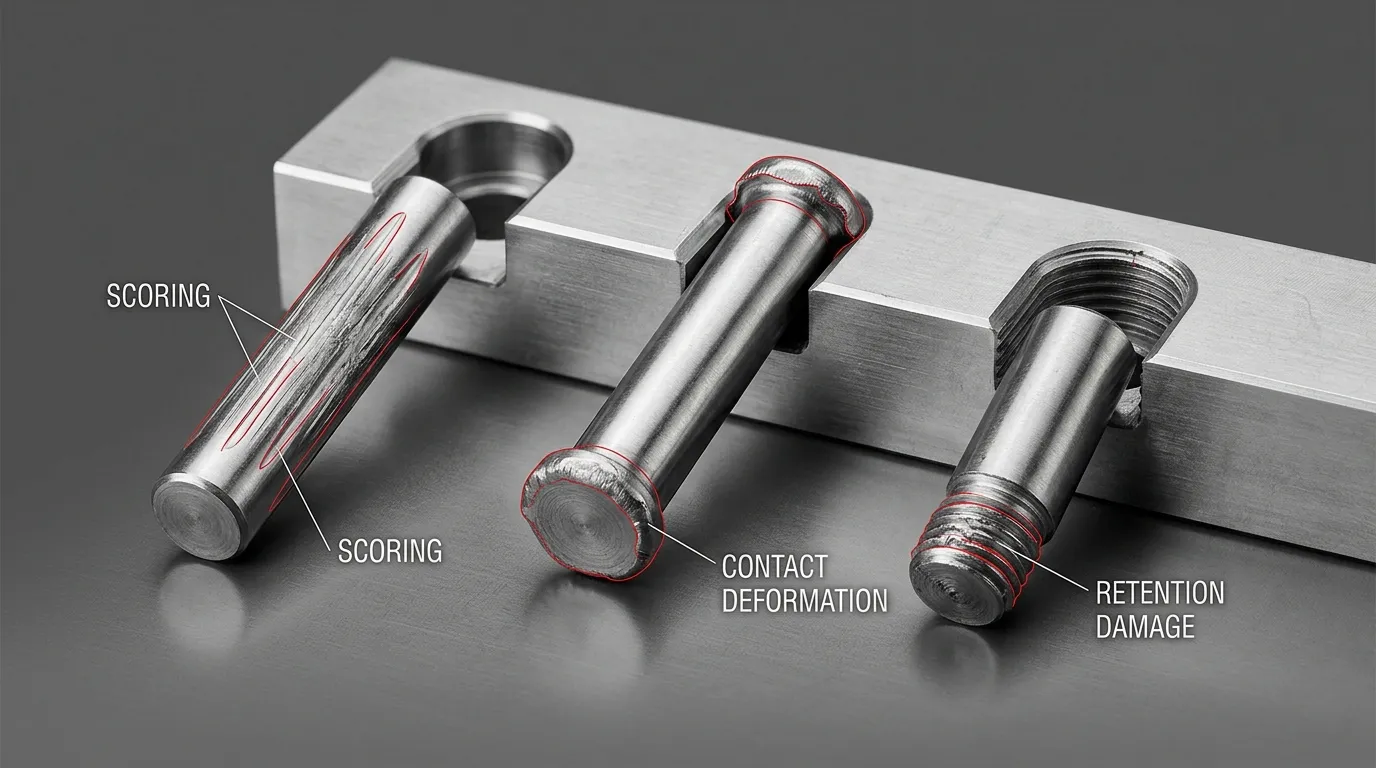
| Deformed contact face | Effective height and load distribution may have changed | Measure, inspect the mating surface, and normally replace |
| Severe scoring or galling | Surface damage may be progressing or transferring material | Measure and determine whether continued service is acceptable |
| Diameter, length, or projection outside specification | The pin no longer conforms to the approved design | Replace or follow an approved repair process |
| Loose thread, damaged shoulder, or incomplete seating | The pin cannot hold its intended position | Correct the retention problem and replace damaged parts |
| Uneven or abnormal contact pattern | Contact may be off-centre or load may be distributed incorrectly | Inspect the pin group, seat, and related alignment components |
Cracks, Chipping, Permanent Deformation, or Severe Corrosion
Cracks and chipped contact areas indicate more than ordinary surface polishing. They can reduce the pin’s load-carrying section and create stress concentrations during repeated contact.
Permanent deformation is another strong replacement sign. Examples include:
- a mushroomed or peened contact face;
- visible bending;
- a damaged shoulder;
- a contact face that is no longer flat where flat contact is required;
- material displaced around the edge of the pin.
Severe corrosion also requires attention. Light staining may be removable, but deep pitting can reduce dimensions, interrupt contact, or prevent the pin from seating correctly. Do not establish a universal allowable pit depth. Compare the remaining geometry and surface condition with the drawing and the mold’s approved maintenance requirements.
Measurable Diameter, Length, Projection, or Straightness Change
Visual inspection cannot show every form of wear. A pin may look acceptable while its effective height, outside diameter, or straightness has changed enough to affect operation.
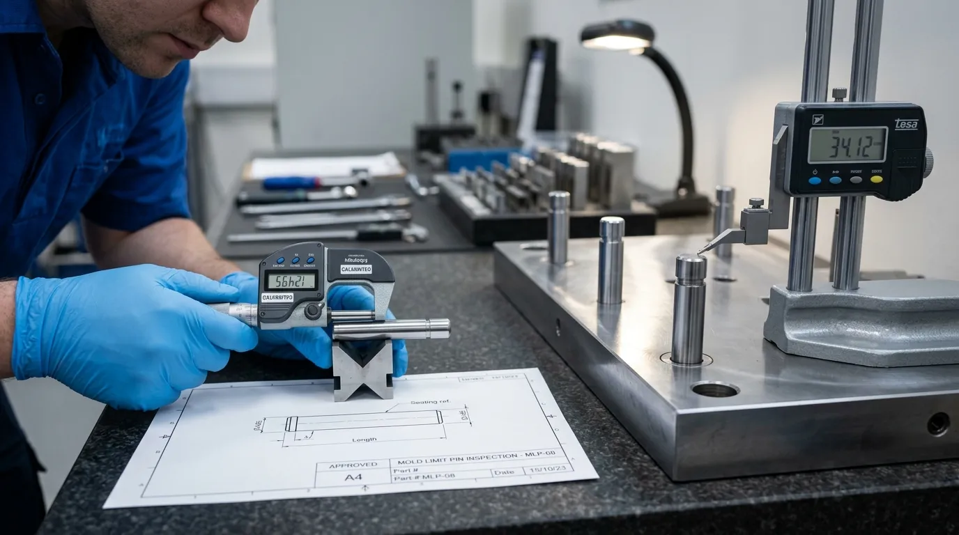
Measure accessible diameters at more than one axial position and in more than one direction. This helps reveal localized wear and out-of-roundness that a single reading could miss.
Also distinguish between:
- overall pin length, which describes the complete component;
- installed projection, which is the amount extending from its seating reference;
- effective stopping height, which includes seating condition and contact-face geometry.
A pin can retain its nominal overall length while losing effective height through deformation, loose seating, thread damage, or wear at the contact face.
Straightness or runout should be checked when the design, access, and required accuracy justify it. The correct method depends on the geometry and specification. Do not assume that one instrument or setup is suitable for every pin.
Loose Retention, Damaged Threads, or Uneven Seating
A limit pin may change position even when the main shaft shows little visible wear. Inspect every feature that establishes or retains its axial position.
Szukaj:
- damaged or stripped threads;
- repeated loosening;
- an incomplete shoulder contact;
- debris under the seating face;
- fretting around the mounting area;
- plate-bore wear;
- damage to a retaining fastener or locking feature;
- unexpected projection differences between similar pins.
Do not solve repeated loosening by applying an arbitrary tightening value. The correct retention method and any torque requirement must come from the mold design or an approved maintenance procedure.
Operating and Part-Quality Symptoms That Should Trigger Inspection
Changes in mold behaviour can indicate that a stopping, guiding, locating, or retaining component is deteriorating. They should start an investigation, not end it.
| Objawy | What it may indicate | What it does not prove |
| Harder or louder contact | Changed projection, deformed contact face, loose retention, or another closing issue | That the limit pin alone is defective |
| Binding or uneven movement | Misalignment, contamination, guide-system wear, or deformed components | That replacement of the limit pin will restore movement |
| Vibration | Uneven contact, looseness, guide wear, or machine-related conditions | A specific failed component |
| Flash or parting-line mismatch | Tooling alignment, closing, pressure, wear, or process problems | Direct limit-pin failure |
| Dryf wymiarowy | Tooling wear, movement changes, temperature, process variation, or measurement issues | That one pin is outside specification |
| Repeated adjustment | A component may be moving, wearing, or losing its set position | The root cause without inspection |
Compare the current sound, movement, and part condition with the mold’s documented normal operation. A new impact sound accompanied by reduced pin projection and contact-face deformation is meaningful. The same sound without physical or dimensional evidence requires a wider check.
Where symptoms point toward guide-system wear, inspect the dedicated Sworznie i tuleje formowe rather than treating the limit pin as the default cause.
How to Inspect a Mold Limit Pin Before Replacing It
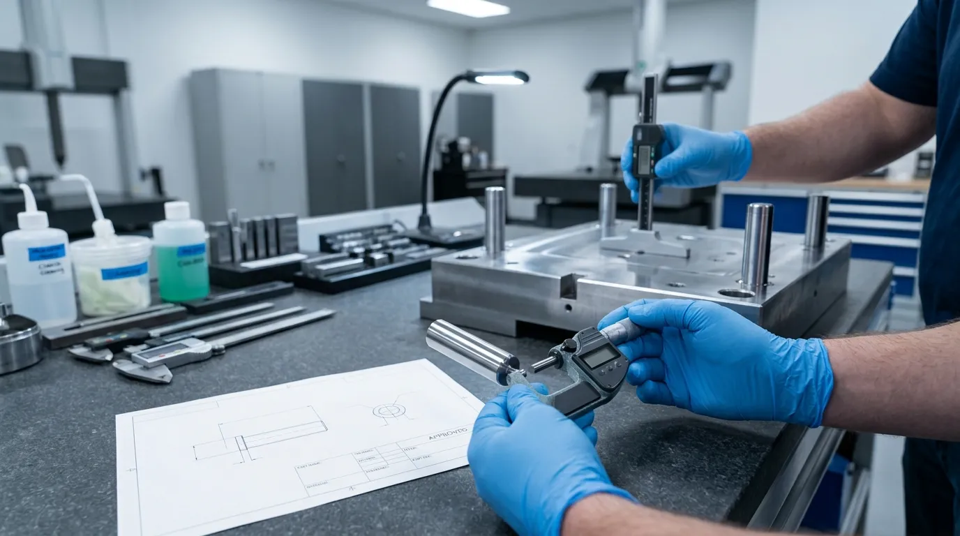
Servicing a mold can expose personnel to mechanical, hydraulic, pneumatic, electrical, thermal, or stored energy. Isolate the equipment according to the applicable local procedure before inspection. For US workplaces, OSHA’s hazardous-energy guidance explains the need to control unexpected energization and stored-energy release during servicing.
A practical inspection sequence is:
- Confirm the pin’s identity and function.
- Record its installed condition.
- Clean the accessible inspection surfaces.
- Inspect structural and surface condition.
- Measure the specified geometry.
- Inspect retention and seating features.
- Check the mating contact surface.
- Compare related pins where they share a stop plane or load.
- Review previous inspection and maintenance records.
- Assign a disposition: monitor, investigate, schedule replacement, or remove immediately.
Document the Pin in Its Installed Condition
Record evidence before removing the pin because removal may change its seating position or erase useful contact information.
Capture:
- mold identification;
- pin part number and location;
- drawing revision;
- installed projection;
- orientation;
- visible contact pattern;
- looseness or movement;
- current operating symptoms;
- photographs of abnormal damage where useful.
If several pins appear to contact the same plate or stopping surface, record their projections and contact patterns as a group.
Measure Geometry Against the Drawing
Use the current approved drawing whenever possible. A worn sample should not be the only reference because copying its present dimensions can reproduce material loss or deformation.
A useful inspection record can include:
| Cechy | Drawing or approved value | Current result | Previous result | Disposition |
| Outside diameter | ||||
| Całkowita długość | ||||
| Installed projection | ||||
| Straightness or runout | ||||
| Thread or shoulder geometry | ||||
| Contact-face condition |
ISO 286-1 provides terminology and principles for linear-size tolerances and fits. It does not provide a universal limit-pin wear allowance. The component drawing still defines the applicable acceptance limits.
Where a measurement lies close to a specification boundary, the decision should account for measurement uncertainty. ISO 14253-1 addresses conformity decisions involving measurement uncertainty, while NIST guidance on dimensional measurement equipment explains why equipment selection must match the feature and required accuracy.
A micrometer may be suitable for accessible outside diameters, while more complex geometry may require another setup. The wider Części do precyzyjnych form guide covers drawing verification, dimensional inspection, hardness, finish, and quality-control considerations in more detail.
Inspect the Seat, Retention, and Other Pins
Do not inspect the pin in isolation. Check the surface and structure that establish its position and receive its load.
Inspect for:
- indentation or cracking at the mating stop surface;
- uneven witness marks;
- embedded debris;
- a damaged seating face;
- a worn or enlarged plate bore;
- thread damage;
- loose retaining hardware;
- corrosion around the mounting interface;
- unequal contact among pins intended to share a stopping plane.
Installing a new pin against a damaged seat can reproduce abnormal contact and shorten the replacement’s usable life.
Replace, Monitor, or Investigate Another Component?
A useful decision separates confirmed pin failure from conditions that only justify further investigation.
| Znalezienie | Recommended disposition | Additional check |
| Crack, chip, permanent bend, severe deformation, or insecure retention | Remove and replace | Inspect the mating surface and surrounding plate |
| Confirmed dimensional nonconformance | Replace or use an approved repair route | Confirm measurement uncertainty and drawing revision |
| Progressive scoring, galling, or projection change | Plan replacement | Review maintenance history and contact conditions |
| Stable cosmetic marks with acceptable dimensions and operation | Continue with monitoring | Establish the next inspection point |
| Noise, flash, vibration, or mismatch without direct pin evidence | Investigate other components | Check guide pins, bushings, seats, plates, and process conditions |
| Measurement close to a specification limit | Apply an approved conformity rule | Verify equipment suitability and uncertainty |
Polishing or regrinding is not automatically safer or cheaper than replacement. Material removal can change diameter, length, contact geometry, finish, and load distribution. Rework should only be used when an approved procedure defines the allowable material removal, required final dimensions, surface condition, heat-treatment requirements, and post-rework inspection.
The same principle applies to maintenance intervals. Cycle count can help schedule inspections, but it should not replace evidence from condition, measurement, and operating history.
Should You Replace One Pin or Check the Full Pin Group?
One worn pin does not automatically mean every pin must be replaced. The decision depends on how the pins function together.
Check whether the pins:
- share the same stopping plane;
- carry load at the same stage of movement;
- require matched effective heights;
- show similar wear patterns;
- contact the mating surface evenly;
- have a group-replacement requirement on the drawing or maintenance specification.
Individual replacement may be appropriate when the remaining pins are dimensionally conforming, securely retained, and not required to be supplied as a matched set.
A coordinated replacement may be more appropriate when unequal effective heights are redistributing load, several pins show progressive wear, or the design requires matched contact. Measure first rather than assuming either approach is universally correct.
Record the Replacement Specifications Before Ordering
Once replacement is justified, document the required configuration before contacting a supplier.
Zawieraj:
- mold identification and pin part number;
- current drawing revision;
- outside diameter and tolerance;
- całkowita długość;
- installed projection or effective height;
- contact-face shape;
- thread, shoulder, or retention details;
- material;
- heat treatment and hardness;
- required surface finish or treatment;
- quantity;
- matched-height requirements;
- inspection-document requirements.
Standard availability depends on the full specification, not nominal diameter alone. A pin with the correct diameter but the wrong projection, contact face, material condition, or thread may not be interchangeable.
SunshinePro’s listed mold limit pin uses S45C and displays product-specific diameter, length, and hardness information. The page also describes precision grinding, formed threads, vacuum heat treatment, standard sizes, and non-standard customization. These details apply to that listed product and should not replace the requirements on the actual mold drawing.
Correct the Damaging Condition Before the New Pin Returns to Service
Replacement is incomplete if the condition that damaged the original pin remains in the mold.
Before returning the mold to production:
- repair or approve the mating stop surface;
- correct loose or damaged retention;
- remove contamination from the seating interface;
- verify the specified installed projection;
- compare pins that share a stop plane;
- investigate abnormal guide-system movement;
- record the replacement date and baseline measurements.
The strongest replacement decision is based on direct evidence: structural condition, measured geometry, secure retention, correct projection, and acceptable mating contact. Once those requirements are documented, a drawing-based replacement request can be submitted through SunshinePro’s Strona kontaktowa.
Udostępnij:


Scenariusz: Tonmoy
WIADOMOŚCI
UZYSKAJ USŁUGĘ
Z wysokiej jakości częściami dostosowanymi do każdego budżetu oraz przyjaznym personelem przeszkolonym, by Twoja wizyta była poinformacyjna i bezproblemowa.
