



Perforation Punch Pin Design for Repeated Small-Hole Patterns
Perforation punch pin design is not simply a matter of choosing a small diameter and a hard material. A reliable design must coordinate the hole pattern, sheet material, Geometria dziurkarki, support system, combined cutting force, Oczyszczanie, slug path, and maintenance method.
The challenge becomes greater as hole diameter decreases or more holes are punched during each stroke. Długi, unsupported tip may deflect. A dense cluster can exceed press capacity or distort the sheet. Small slugs may clog the die or return to the work surface. The punch therefore has to be designed as part of the complete cutting system.
Dla szerszych informacji o punchach, stripper systems, Elementy przewodnie, and other tooling parts, zobacz Przewodnik po komponentach matrycy (wnioskowane). This guide focuses specifically on punch pins used for repeated small-hole patterns.
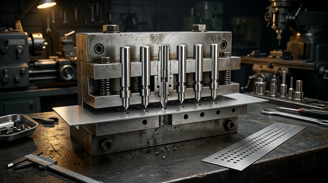
What Must Be Designed Together in a Perforation Punching System?
A perforation punch pin forms one part of a load path that extends through the tool:
- The cutting tip enters the sheet.
- The punch shank transfers the cutting load upward.
- The punch plate locates and retains the pin.
- The backing plate supports the punch against axial reaction.
- The stripper controls the sheet and may guide the punch near its tip.
- The die opening provides the opposing cutting edge.
- The slug passes through the die relief and exits the tool.
A weakness in any one part can affect the entire operation. A strong punch material will not prevent failure if the working tip is too long, the stripper allows lateral movement, or the die opening is misaligned. A correctly sized pin can still produce unstable results if several tips create excessive combined force or if the slug path becomes blocked.
This is why perforation tooling should not be treated as an isolated component-selection exercise. General die construction and die-type decisions are covered more broadly in the Przewodnik po formach wybicia. Proszę, the design starts with the repeated hole pattern and works inward toward the punch pin.
Określ wzór otworów i wymagania dotyczące arkusza przed zaprojektowaniem sworzni
The working diameter is only one input. Before selecting a pin architecture or material, define the conditions that control the cutting operation.
The design package should include:
- Materiał i stan arkusza
- Nominalna tolerancja grubości i grubości arkusza
- Hole diameter, Kształt, and dimensional tolerance
- Kąt nachylenia otworów w każdym kierunku
- Pozostałe materiały między sąsiednimi otworami
- Pattern arrangement, including aligned or staggered rows
- Wymagana przestrzeń otwarta
- Kierunek zażaru i dopuszczalna wysokość zadziorna
- Wymagania dotyczące płaskości arkusza
- Oczekiwany wolumen produkcji
- Dostępna liczba pras i stacji
- Wymagania dotyczące smarowania i czystości
- Planowana metoda ostrzenia i wymiany
These inputs are connected. Changing the sheet thickness affects cutting force, slug geometry, practical hole size, and die clearance. Reducing hole pitch leaves less material between adjacent openings and may weaken both the sheet and the die. Increasing the number of tips raises the combined cut perimeter and total force.
Hole Size, Materiał, and Thickness Set the First Feasibility Check
A small hole is more difficult to punch when its diameter approaches or falls below the sheet thickness. The exact practical limit depends on the work material, punch material, Wskazówki, Przebieg trasy, tool construction, and required hole quality.
A hard or high-strength sheet generally creates greater cutting load than a softer material of the same thickness. A small punch cross-section must carry that load without bending, odpryskiwanie, or breaking. Guided tooling may support a more demanding diameter-to-thickness relationship than a long, non-guided punch, but guidance does not eliminate the need for sufficient punch strength.
Źródła techniczne, takie jak wytyczne MISUMI dotyczące Dziurkowanie o małej średnicy emphasize short working sections, stepped support, and controlled slug removal. Supplier ratios can be useful for an early feasibility check, but they should not be treated as universal design limits.
Pitch, Remaining Web, and Flatness Define the Pattern-Level Risk
Hole pitch is the centre-to-centre distance between adjacent perforations. The remaining web, sometimes called the bridge, is the material left between their edges.
A pattern may contain individually feasible holes but still be difficult to manufacture if the web becomes too narrow. Dense perforations can:
- Zmniejszenie sztywności blachy lokalnej
- Osłab materiał matrycy między otworami
- Zwiększ ryzyko interakcji dziur
- Wytwarzaj rozciąganie lub falowanie arkusza
- Stwórz konserwowanie olejem na większym panelu
- Skoncentruj obciążenie cięcia w jednym obszarze narzędzia
Aligned rows and staggered rows do not distribute load in the same way. A staggered pattern may improve open-area distribution or reduce direct alignment of weak sections, but it does not automatically solve distortion. The finished panel’s flatness requirement must be considered with the complete punching sequence.
Wybierz architekturę pinów dziurkacyjnych, która wspiera mały roboczy grot
A perforation pin normally contains several functional regions:
- Robocza końcówka, która tworzy otwór
- Przejście lub ramię za czubkiem
- Większy trzpień, który przenosi i podtrzymuje obciążenie
- Funkcja zatrzymania, która lokalizuje dziurk w płycie dziurkaczowej
- Dodatkowy dodatek na regulację lub ponowne szlifowanie tam, gdzie jest to konieczne
The small working portion should be only as long as the operation needs. Extra unsupported length increases sensitivity to lateral movement and bending. The required length must still allow suitable penetration, stripper guidance, withdrawal, and future sharpening.
Prosta, Stepped, and Multi-Step Pins Serve Different Section Sizes
| Architektura pinów | Typowa logika projektowania | Główna zaleta | Główne ograniczenie |
|---|---|---|---|
| Prosty kołek | Przekrój roboczy i trzpień mają taki sam lub podobny przekrój poprzeczny | Prosta geometria i produkcja | Bardzo mała całkowita część może być pozbawiona sztywności |
| Krokowy sworzeń | Mała końcówka robocza jest podparta przez większy trzonek | Lepsze wsparcie za sekcją tnącą | Pozycja barku i przejście wymagają starannego zaprojektowania |
| Sworzeń wielostopniowy | Kilka przejść łączy mały czubek z dużo większym korpusem | Bardziej stopniowe zmiany między bardzo różnymi sekcjami | Bardziej złożona geometria i inspekcja |
Dyskusja MISUMI o Konstrukcja dziurkarki z dziurkami distinguishes straight, krok, and multi-step punches according to the strength and size of the functional section.
A stepped punch is often considered when the required hole is too small for a long straight pin to remain sufficiently rigid. The larger shank provides support, while the smaller section performs the cut. The transition should transfer load without creating an unnecessarily sharp stress concentration.
Długość pracy i geometria przejścia Kontrola odchylenia i naprężeń
Two punches with the same tip diameter can behave very differently if one has a much longer unsupported working section.
As the slender section becomes longer, the pin becomes more vulnerable to:
- Boczne ugięcie
- Niewyrównanie z otworem matrycy
- Nierówne boczne zużyciu
- Odłubowanie krawędzi cięcia
- Uszkodzenie zmęczenia
- Zginanie podczas zdejmowania
The transition behind the working tip also matters. An abrupt reduction in section can create a highly stressed area. A better-supported transition distributes the load into the larger shank while preserving the required access to the sheet and stripper.
There is no single universal working-length ratio for every material and application. The final geometry must account for penetration, Grubość arkusza, stripper position, guidance length, regrinding allowance, and the actual load on the tip.
Guide, Zachowaj, and Back the Punch Through the Full Stroke
Small punches require both axial and lateral support.
The punch plate retains and locates the shank. The backing plate supports the punch against cutting reaction. The stripper controls the sheet during withdrawal and may guide the punch close to the cutting region. These elements must remain aligned with the die opening.
Even a correctly dimensioned pin can fail if the support system allows side loading.
Naprowadzanie zniszczacza ogranicza wędrówki w pobliżu końcówki tnącej
A stripper-guided punch passes through a controlled opening in the stripper plate before entering the sheet. This close support reduces the distance over which the small tip can move laterally.
Nota techniczna MISUMI o Wskazówki do usuwania do dziurkaczy z blankami otworów explains that small punches are especially vulnerable to lateral movement. The stripper can reduce that movement, but only when the stripper itself moves accurately.
If the stripper tilts, shifts, or has excessive clearance, it may transfer error to the punch rather than correcting it. The stripper opening, punch shank, and die opening must therefore be treated as one alignment system.
Płyta dziurkowa i płyta podkładowa uzupełniają osiowy układ obciążenia
The punch plate positions the pin, but it may not provide sufficient resistance to concentrated axial load by itself. A small punch head or shank can create high local pressure behind the pin.
A backing plate spreads this reaction into a stronger supporting area. Without adequate backing, the punch may indent or sink into the holder, changing its working height and alignment.
Wytyczne MISUMI dotyczące Konstrukcja płyty podkładowej highlights this issue for punches with small supporting cross-sections.
The load path should remain flat, rigid, and correctly located. A hard punch placed against a weak or poorly supported holder can still lose position under repeated loading.
Dopasuj liczbę kolków i układ wzoru do dostępnej siły wybijania
A cluster punch produces several holes in one stroke. This can reduce the number of press cycles required, but the press must cut the combined perimeter of all engaged tips.
The total load is not determined by hole count alone. It depends on:
- Całkowity obwód przecięcia
- Grubość arkusza
- Odporność na ścinanie materiału roboczego
- Liczba końcówek tnących jednocześnie
- Ostrość uderzenia
- Porozumienie
- Warunki demontażu
- Wydajność narzędzi i prasy
Adding more tips may increase output per stroke, but it also raises cutting load, slug volume, maintenance exposure, and the possibility of sheet distortion.
Estimate Force from Total Cut Perimeter, Not Hole Count Alone
A conceptual punching-force relationship is:
Siła wybijania ≈ całkowity obwód cięcia × grubość blachy × odporność materiału na ścinanie
For a cluster, the total cut perimeter is the sum of the perimeters of all tips engaged during the same part of the stroke.
This means ten small round holes do not create the same load as ten slots with a much greater combined perimeter. Two patterns with similar open area may also require different force because their edge lengths differ.
Precyzja partnera Nawigacja klastrowego wybijania uses total cutting perimeter as a central force-planning factor and recommends checking cluster load against the machine and station limits.
The calculation should be treated as an engineering estimate. The actual tool must also account for stripping force, load balance, press condition, and the manufacturer’s tooling limits.
Rozłożenie i rozkład obciążenia mogą zmniejszyć problemy na poziomie wzorców
If every adjacent tip enters the material at the same time, cutting load may be concentrated within a small area. This can increase peak force and stretch the sheet around the pattern.
Possible design responses include:
- Podzielenie wzoru na więcej niż jedną stację
- Używaj mniej aktywnych końcówek
- Układanie rzędów tak, aby zaangażowanie było rozłożone
- Rozstawianie długości końcówek tam, gdzie pozwala na to system narzędziowy
- Wyważenie wzoru wokół środka narzędzia
- Zmiana sekwencji uderzeń
These methods can reduce local concentration, but they may also add tool complexity or change the loading sequence. They must preserve the finished hole locations and part geometry.
Informacje Wilson Tool o Perforacja narzędziami klastrowymi also identifies sheet stretch and oil-canning as practical concerns in dense perforation work.
Skoordynuj oczyszczanie matryc z ewakuacją ślimaków
The punch and die opening form one cutting pair. Clearance between them influences cutting load, fracture behaviour, Formowanie żarna, Zużycie narzędzi, and slug release.
Repeated small-hole patterns make waste handling especially important. A cluster with 20 tips creates 20 slugs during each complete punching cycle. Even when each slug is small, the cumulative waste flow can become substantial.
The die must provide:
- Odpowiedni prześwit na cięcie
- Odpowiedni kraj
- Relief poniżej krawędzi tnącej
- Ciągła trasa wyjścia
- Dostęp do inspekcji i czyszczenia
- Ochrona przed recyrkulacją ślimaków
Clearance Must Be Verified for the Material, Grubość, and Required Edge
Clearance is normally considered per side between the punch and die cutting edges. The appropriate value depends on the sheet material, Grubość, Wymagany warunek krawędzi, punch condition, and tooling method.
Clearance that is too small may increase force and wear. Clearance that is too large may increase burrs, edge rollover, lub zmienność wymiarowa. As the punch and die wear, effective clearance changes even if the original dimensions remain correct.
For this article, the important point is that the pin diameter cannot be finalized independently from the die opening. Exact clearance values require material- and application-specific calculation and validation.
Każdy dodatkowy otwór dodaje kolejny ślimak, który musi niezawodnie wyjść
Small slugs can:
- Gromadzenie w ograniczonej liczbie przejść na kościach
- Most nad wąskimi odcinkami reliefowymi
- Zgęście w zator
- Trzymaj się czołówki uderzeniowej
- Powrót na powierzchnię roboczą
- Uszkodzenie prześcieradła podczas późniejszego uderzenia
The die relief should allow slugs to move away without trapping one another. Tool access should permit cleaning before debris raises the cutting load or damages the punch.
Slug pulling requires particular attention. A slug that follows the punch upward may be pressed back into the sheet or trapped between the tool and workpiece. Geometry, Dostęp, Smarowanie, Stan powierzchni, and waste-path design can all influence this behaviour.
Wybierz materiał sworzni i obróbkę powierzchni według oczekiwanego trybu awarii
The hardest available punch material is not automatically the best choice. Material selection should respond to the dominant failure risk.
Common risks include:
- Zużycie ścierne
- Zużycie lub uszkodzenie adhezji
- Edge chipping
- Uszkodzenie zmęczenia
- Odkształcenie plastyczne
- Wpływ niedopasowania
- Korozja lub uszkodzenia powierzchni
A material that resists wear well may be less tolerant of shock or side loading. A tougher material may survive misalignment better but require more frequent sharpening.
Stal narzędziowa, HSS, and Carbide Balance Wear and Toughness Differently
| Material family | Przydatne cechy | Główne wyzwanie projektowe |
| Stal narzędziowa | Broad balance of toughness, Odporność na zużycie, Obróbka cieplna, and regrindability | Wydajność zależy w dużej mierze od jakości i obróbki cieplnej |
| Stal szybkotnościowa lub metalurgia proszkowa | Mogą zapewnić wyższą odporność na zużycie, zachowując jednocześnie użyteczną wytrzymałość | Koszty i trudność obróbki mogą wzrosnąć |
| Węglik | Wysoka odporność na zużycie i wytrzymałość na ściskanie | More sensitive to impact, odpryskiwanie, and alignment errors |
Carbide may be suitable for stable, ścierny, high-volume applications, but it is not a universal solution for every small hole. A slender carbide tip exposed to side load or impact may chip where a tougher steel punch would survive.
The selection should consider the sheet material, working-tip diameter, Długość bez podparcia, Wskazówki, Smarowanie, press condition, and previous failure history.
SunshinePro's Niestandardowy sworzeń dziurkowy listy stron SKH51, SKH9, DC53, ASP-grade materials, and carbide among its stated material options. Final suitability still has to be confirmed against the actual drawing and application.
Wykończenie powierzchni, Powłoka, and Lubrication Address Surface Interaction
Surface finish influences friction, Materiał przechwyt, Premiera, and the condition of the substrate beneath a coating. A smoother working surface may help reduce adhesion in suitable applications, but finish alone cannot correct an unsupported tip or misaligned die.
Coatings such as TiN, TiCN, and DLC may be considered for selected wear or friction conditions. Their value depends on:
- Podłoże dziurkowe
- Materiał obrabianego
- Przygotowanie powierzchni
- Geometria krawędzi
- Smarowanie
- Temperatura
- Uderzenie i boczne obciążenie
- Przyczepność powłoki
A coating should not be used as a structural repair. It cannot compensate for excessive working length, poor stripper guidance, weak backing, or incorrect clearance.
Lubrication is also part of the system. It can reduce friction, Zużycie kleju, and stripping resistance, but the lubricant must be compatible with the work material, downstream process, and cleanliness requirements.
Design the Tool for Replacement, Ostrzenie, and Inspection
Perforation tooling should be serviceable before the first production run begins. A design that performs well initially but cannot be repaired economically may create unnecessary downtime later.
The maintenance plan should address:
- Wymiana pojedynczych sworzni
- Dostępność zapasowych końcówek
- Dodatek na ostrzenie
- Regulacja długości po ponownym szlifowaniu
- Dostęp do zatrzymanych pinów
- Identyfikacja końcówki
- Punkty inspekcyjne
- Limity zastępcze
Stałe narzędzia z wieloma końcówkami i wymienne końcówki tworzą różne modele konserwacji
A fixed multi-tip punch may be compact and mechanically simple. If one tip is damaged, jednak, the repair may affect the complete tool.
Replaceable-tip systems allow individual punches to be changed without discarding the whole cluster body. Wilson Tool describes replaceable configurations among its perforation-tool options.
Replaceable tips are not suitable for every pattern. Very close spacing may leave insufficient room for individual retention features. The design must also provide access for removal, accurate location after replacement, and a practical spare-parts system.
The best configuration depends on pattern density, Częstotliwość konserwacji, tool size, and the cost of replacing one damaged position compared with servicing the complete assembly.
Ponowne szlifowanie zmienia więcej niż tylko krawędź tnącą
Sharpening removes material from the cutting face. This changes the punch length and may alter penetration, Korekta, stripper relationship, or the available guided length.
After regrinding, Sprawdź:
- Średnica lub profil grotu
- Stan nowoczesności
- Pozostała długość robocza
- Prostość
- Koncentryczność między końcówką a trzonkiem
- Warunek przejścia
- Uszkodzenia powierzchniowe
- Funkcja retencji
- Całkowita długość lub pozycja regulacji
A pin should not remain in service merely because its edge can still be sharpened. If the remaining geometry no longer provides sufficient support or alignment, replacement may be safer than another regrind.
Diagnozowanie problemów z wzorcami poprzez przegląd zmiennej projektowej za nimi
Production symptoms rarely identify one guaranteed root cause. They do indicate which design relationships should be checked first.
| Production symptom | Możliwe przyczyny projektowe | Punkty do przejrzenia |
| Wędrowanie dziurkaczem lub zmiana pozycji otworu | Long unsupported tip, weak stripper guidance, Niedopasowanie | Długość robocza, stripper clearance, Wyrównanie płyt, Koncentryczność |
| Powtarzające się łamanie ciosu | Excessive force, Boczny ładunek, Stężenie naprężeń, Niewystarczająca wytrzymałość | Tip length, Przejście, Materiał, Dostęp, press alignment |
| Edge chipping | Brittle material, Wpływ, poor edge condition, Nierówny kontakt | Jakość materiałowa, Obróbka cieplna, punch face, Przebieg trasy |
| Szybki wzrost zadziorów | Punch or die wear, changing effective clearance | Cutting edges, Otwarcie, sharpening interval |
| Galling or material pickup | Klej roboczy, poor finish, unsuitable lubrication | Wykończenie powierzchni, Powłoka, Smar, Dostęp |
| Ściąganie ślimaków | Przyczepność, Nieodpowiednie prześwitanie, poor release conditions | Punch face, Otwarcie, Smar, slug path |
| Blokada | Ograniczona ulga lub nadmierne gromadzenie ślimaków | Kraj, Relief, exit path, cleaning access |
| Nierówne dziury na całym skupisku | Unbalanced load, different tip lengths, Ugięcie płyty | Tip projection, Wsparcie wspierające, tool rigidity |
| Falistość arkusza lub konserwowanie olejem | Dense pattern, concentrated engagement, insufficient web | Pitch, pattern sequence, active tip count |
| Nadmierne obciążenie prasy | Too much simultaneous cut perimeter, dull edges, Słaby prześwit | Pin count, cutting perimeter, Materiał, Stan krawędzi |
For a broader review of fractured or chipped punches, Zobacz Pęknięcie dziurkownika w matrycach tłoczących. The focus here should remain on the design variables created by small diameters and repeated patterns.
Przygotuj gotowy dla dostawcy rysunek i pakiet RFQ
A supplier cannot evaluate a perforation application from the punch diameter alone. The same nominal pin may behave very differently in thin aluminium, high-strength steel, Powłoka powlekana, or a dense multi-tip cluster.
Przydatny pakiet RFQ powinien zawierać:
- Materiał i stan obrabianego przedmiotu
- Grubość nominalna i tolerancja
- Hole shape, Wymiary, oraz tolerancje
- Pełny rysunek wzoru
- Rozbiór i pozostała sieć
- Wymagany kierunek zadziorów
- Wymóg płaskości lub zniekształcenia
- Intencja narzędzia z pojedynczym końcem lub klastrowym
- Średnica i długość końcówki roboczej
- Wymiary trzonka
- Geometria kroków i przejść
- Retention method
- Die-opening and clearance information, jeśli już zdefiniowano
- Typ prasy i odpowiednia pojemność
- Wielkość produkcji
- Warunki smarowania
- Aktualna historia awarii projektów zastępczych
- Wymagane materiały i obróbka cieplna
- Wymagania dotyczące wykończenia powierzchni lub powłoki
- Wymagane cechy inspekcyjne
- Strategia ponownego szlifowania i zamiennych sworzni
- Rysowanie, rewizja i kryteria akceptacji
Include the Pattern, Prasa, and Failure History—not Only the Pin Diameter
For a replacement project, provide the complete pattern and production context wherever possible. Useful supporting information may include:
- Zdjęcia zużytego lub uszkodzonego puncha
- Zdjęcia uszkodzonej przekłady
- Lokalizacja awarii w wzorcu
- Obecna historia ostrzenia
- Progres burra
- Dowody blokady ślimaka
- Zmiany obciążenia prasy
- Istniejące wymiary dziurkaczy i matrycy
This information helps distinguish a material problem from a geometry, Przebieg trasy, Dostęp, or waste-flow problem.
Potwierdzenie zakresu produkcji i kryteriów akceptacji przed rozpoczęciem produkcji
The RFQ should state whether the supplier is being asked to:
- Wykonanie przypinki do zatwierdzonego rysunku
- Przegląd wykonalności geometrii pinu
- Polecam materiał lub powłokę
- Wykonaj zastępcze piny z próbki
- Dokumentacja inspekcji dostaw
- Udział w szerszym projektowaniu układów lub aplikacji
These are different scopes of responsibility.
SunshinePro twierdzi, że produkuje Niestandardowe sworznie do dziurkania from customer drawings and lists CNC machining, EDM, precyzyjne szlifowanie, Obróbka cieplna, and optional coatings on the product page. Project-specific material, tolerancja, Zakończenie, coating suitability, and inspection requirements should still be confirmed against the drawing.
For a technical review or quotation, provide the pattern drawing, sheet material and thickness, Geometria dziurkarki, press information, and any current failure details through the Strona kontaktowa SunshinePro.
Udostępnij:



Napisane przez Sunshine
W Sunshine, Jesteśmy profesjonalnym producentem i dostawcą komponentów do precyzyjnych form, oferując szeroką gamę produktów do tłoczenia i formowania wtryskowego. Naszym głównym celem są formy do dziurkania, Sworznie wyrzutowe i tuleje, oraz słupy i tuleje. Dzięki zaawansowanej obróbki CNC, Ścisła kontrola jakości, oraz silne możliwości produkcyjne, Zapewniamy niezawodność, Części o wysokiej precyzji, wraz ze standardowymi komponentami dostępnymi na stanie, zapewniającymi szybkie i efektywne globalne dostawy.
WIADOMOŚCI
UZYSKAJ USŁUGĘ
Z wysokiej jakości częściami dostosowanymi do każdego budżetu oraz przyjaznym personelem przeszkolonym, by Twoja wizyta była poinformowana i bezproblemowa.
