



Układ pinów do pozycjonowania formy: Odstępy i kontrola ograniczeń
A reliable mold positioning pin layout controls the required movement with the fewest necessary locating constraints. For a mold plate or removable insert, that usually means establishing the main in-plane position with a primary locator and preventing rotation with a secondary locator that does not create unnecessary binding.
Pin spacing should be wide enough to reduce angular sensitivity, but it cannot be chosen from spacing alone. Plate strength, Dane funkcjonalne, Kanały chłodzące, screws, Elementy wyrzutnika, Ruch termiczny, machining access, and future pin removal all affect the final layout.
This guide focuses on fixed locating or dowel features used to position mold plates, Wkładki, and tooling components. For broader guidance on moving mold-half alignment, operating fit, zużycie, oraz konserwację, Zobacz Sworznie i tuleje formowe (wnioskowane).
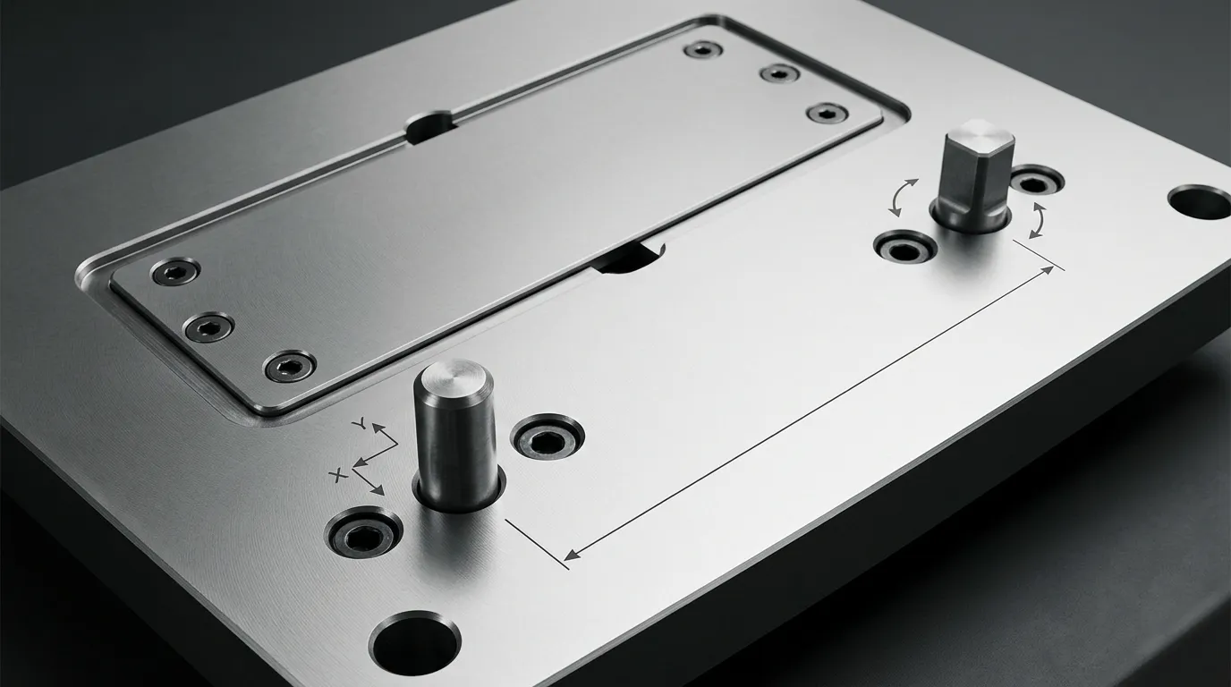
Co musi kontrolować układ pinów pozycyjnych
Before placing any pin, define what the component is allowed to do.
A plate or insert resting on a mating surface can still move in three ways within that plane:
- translate along the X direction;
- translate along the Y direction;
- rotate around an axis perpendicular to the plate.
The positioning-pin layout must control those three in-plane movements. The mating face establishes the seating plane, while screws or clamps retain the component against that face.
This distinction matters because not every mold component performs the same task.
Separate Locating, Guiding, Fastening, and Load Control
| Cechy | Główna rola | Czego nie należy zakładać, że się dzieje |
|---|---|---|
| Pozycjonowanie lub kołek kołkowy | Ustalenie powtarzalnej lokalizacji płyty lub wkładu | Wymień wszystkie zaciski lub przenieś wszystkie obciążenia operacyjne |
| Sworzeń prowadzący i tulejka | Połowy formy prowadzącej podczas otwierania i zamykania | Zapewnij jedyne stałe miejsce dla wyjmowanej wkładki |
| Śruba montażowa | Zaciskaj lub utrzymuj komponent | Establish precise, repeatable position by itself |
| Blokada boczna lub interlock | Uzupełnia ostateczne pozycjonowanie lub opiera się określonym warunkom bocznym | Zastąpienie poprawnie zdefiniowanego schematu lokalizowania płyt w każdej aplikacji |
A fixed dowel location and a moving guide system may both contribute to alignment, ale rozwiązują różne problemy. Detailed guide-system selection, zużycie, and maintenance belong with Sworznie prowadzące formę, not in the positioning-pin layout itself.
Positioning pins should also not be treated automatically as the main load-carrying elements. Where the mold experiences significant lateral force, final parting-line location or load resistance may require side locks, taper locks, blokady, Ramiona, or other structural features.
Kontroluj trzy ruchy w płaszczyźnie bez dodawania redundantnych ograniczeń
The layout should constrain only the movements that must be controlled.
A common approach is:
- A primary round locator controls translation in X and Y.
- A secondary locator prevents rotation.
- The mating surface controls seating.
- Screws provide clamping or retention.
Adding more tightly fitted pins does not necessarily increase accuracy. If several locators attempt to control the same movement, small differences in hole position, pin size, Temperatura, or machining error can make the component difficult to assemble.
This condition is called overconstraint. Its effects may include binding, forced assembly, internal stress, damaged locating holes, or inconsistent seating.
Wybierz schemat lokalizacji podstawowej i wtórnej
The primary and secondary locators should be selected according to the movement each feature must control.
The correct arrangement depends on component geometry, manufacturing tolerances, Temperatura pracy, assembly frequency, and the distance between locating points. No one arrangement is best for every mold.
Użyj podstawowego okrągłego kołka do ustalenia głównej lokalizacji
The primary round pin normally establishes the main in-plane position. Its cylindrical contact controls movement in two directions.
Place this locator relative to the functional mold feature rather than choosing a location only because it is near a convenient plate corner. Na przykład, if the position of a cavity insert relative to another machined feature is critical, the primary locator should belong to the same functional datum strategy.
The primary location should also be accessible for:
- drilling and reaming;
- Inspekcja wymiarowa;
- Zgromadzenie;
- extraction or replacement;
- repair if the hole becomes worn or damaged.
The physical centre of the plate is not automatically the best primary location. Functional control matters more than visual symmetry.
Zwolnić kierunek wtórny, gdy dwa ciasne miejsca naboje się zacięły
A second locator is required to prevent the component from rotating around the primary pin. The problem is that a second tightly fitted round pin also tries to control X and Y.
If the centre distance between the two holes differs slightly from the centre distance between the two pins, the assembly can bind even when each individual diameter is within tolerance.
A diamond pin, relieved pin, or pin-and-slot arrangement avoids this redundant constraint. The secondary locator contacts the mating feature in the direction required to prevent rotation while allowing clearance in the perpendicular direction.
The relief must be oriented correctly. If the relieved direction is turned the wrong way, the secondary locator may fail to control rotation or may still create the centre-distance conflict it was intended to solve.
ASME Y14.5 provides the formal framework for communicating datum relationships and controlled degrees of freedom. Wskazówki techniczne z FARO o lokalizacji diamentowego pinu also illustrates how directional relief reduces redundant constraint.
| Układ lokalizacyjny | Zachowanie ograniczeń | Główna zaleta | Główne ograniczenie |
| Dwa ściśle dopasowane okrągłe kołki | Oba kołki próbują kontrolować dwa kierunki | Prosta geometria | Czułość na błąd odległości środkowej i zmienność termiczną |
| Okrągły kręgel plus diament lub wydzielony | Primary controls X/Y; secondary controls rotation | Zmniejsza nadmierne ograniczenie | Orientacja reliefu musi być poprawnie zdefiniowana |
| Okrągły sworzeń plus szczelinowy otwór dodatkowy | Slot umożliwia ruch w jednym kierunku | Łatwe do zrozumienia i obejrzenia | Należy kontrolować produkcję szczelin i geometrię styku |
| Okrągły sworzeń plus pływający lokalizator | Cecha drugorzędna kompensuje większe zmienności | Przydatne tam, gdzie odległość środka zmienia się znacząco | Bardziej złożone wymagania dotyczące komponentów i inspekcji |
A floating locator may be useful where centre-distance change is larger than a simple relieved pin can accommodate, such as in long assemblies or components exposed to meaningful temperature differences. It should be selected from verified component data rather than treated as a default solution.
Gdy dwa okrągłe kręgle mogą być nadal odpowiednie
Two round pins are not automatically wrong.
They may work when:
- the pin centre distance is tightly controlled;
- the mating-hole centre distance is controlled from the same datum system;
- one mating condition includes sufficient clearance;
- temperature variation is limited or accounted for;
- the worst-case tolerance condition has been checked;
- the assembly can be installed without forcing.
The decision must be based on the complete tolerance relationship, not nominal dimensions alone.
Ustaw użyteczne rozstawy między pinami i zapobiegaj odwróconemu montażowi
Positioning pins should generally have the longest practical locator baseline.
The locator baseline is the effective distance between the two locating points that resists rotation. Increasing that distance reduces the angular effect of the same amount of hole-position error.
This does not mean the pins should always be placed at the farthest possible corners. Wider spacing is useful only when the resulting locations remain structurally sound, Do wyprodukowania, Dostępny, and clear of other mold systems.
Użyj najdłuższej praktycznej bazy lokalizatora
Consider two locating points separated by a short distance. If the secondary hole shifts slightly, the component rotates around the primary locator.
Now consider the same hole-position shift with the locating points farther apart. The resulting angular change is smaller because the error acts across a longer baseline.
The effect becomes more noticeable at functional features located far from the locators. A small angular error near the pins may produce a much larger positional shift at the opposite end of a long insert or plate.
Praktyczne wskazówki dotyczące umieszczania kołków z MISUMI TechCentral follows the same principle: greater separation between locating points reduces sensitivity to equivalent location error. The exact spacing still depends on the mold design.
Zrównoważenie szerszych odstępów względem ograniczeń płyt i systemu
Useful separation must be balanced against other requirements.
Check whether a wider pin pattern creates any of the following problems:
- insufficient material between the locating hole and a plate edge;
- intersection with a cooling channel or cooling plug;
- conflict with mounting screws or counterbores;
- interference with ejector pins, Sworznie zwrotne, or ejector-plate features;
- conflict with support pillars or load-bearing areas;
- entry into hot-runner manifold, heater, nozzle, or wiring zones;
- blocked sensor or connector access;
- difficult drilling, reaming, or inspection;
- limited extraction access;
- excessive thermal centre-distance change.
A locator placed near a plate edge may improve the angular baseline, but the remaining plate ligament must still withstand manufacturing, Zgromadzenie, oraz warunki eksploatacji. There is no universal edge distance that is safe for every material, Grubość płyty, Średnica sworzni, or load case.
Zrób wzór asymetrycznym dla montażu bezbłędnego
A symmetric two-pin pattern may allow a plate or insert to be rotated or reversed and still appear to fit.
An asymmetric pattern makes the intended orientation unique. This can be achieved by:
- offsetting one locator from the centreline;
- using different distances from adjacent edges;
- staggering the primary and secondary locations;
- combining different locator forms;
- making one orientation physically impossible.
The purpose is not visual variety. It is mistake-proofing.
The pattern should remain unambiguous after the mold has been disassembled for maintenance. A technician should not need to rely on memory or a temporary marking to identify the correct orientation.
Sprawdź układ pod kątem geometrii formy i dostępu do serwisu
After choosing the locating scheme and approximate spacing, review the complete mold assembly in CAD.
A locating hole is not an isolated feature. Its drilling path, Przeciwotwor, mating hole, extraction path, and surrounding plate material may pass through several stacked components.
Stwórz mapę przeszkód w systemie formowym przed wierceniem dowolnego otworu lokalizującego
Show all relevant systems in the same review model:
- Kanały chłodzące, plugs, Osprzęt, and cross-drillings;
- mounting screws and counterbores;
- ejector-pin and return-pin holes;
- ejector-plate movement envelopes;
- filary nośne;
- hot-runner manifolds, nozzles, heaters, and wiring;
- slide and lifter mechanisms;
- sensors and connectors;
- lifting holes and handling features;
- insert pockets and neighbouring replaceable components.
Check hidden paths, not only visible bodies. A proposed locating hole may clear a component in one plate but intersect a cooling drilling or screw counterbore deeper in the stack.
Movement also matters. A hole that is clear in the closed CAD position may conflict with an ejector, slide, or other moving feature during operation or maintenance.
Preserve Plate Strength and Access for Assembly, Inspekcja, and Removal
A workable layout must remain serviceable throughout the mold’s life.
Confirm that:
- the hole can be drilled and reamed from the intended direction;
- inspection equipment can access the locating surfaces or datums;
- the pin has an extraction method when replacement may be required;
- plate separation does not trap the pin unexpectedly;
- the insert can be removed without damaging the locating surfaces;
- the selected engagement length does not obstruct neighbouring features;
- future hole repair, tuleja, or oversize rework remains possible.
A precise location that cannot be machined, measured, or repaired is not a complete design.
Define Functional Datums, Position Tolerances, and Thermal Relief
The locating pattern must be communicated through a drawing or controlled digital model that reflects the intended function.
Pin diameter alone is not enough. The drawing must also control where the holes are located relative to the component’s functional datums.
Wzorzec lokalizujący wymiar z funkcji danych odniesień
Select datums according to how the mold plate or insert works in the assembly.
A practical datum strategy should identify:
- the seating surface;
- the primary functional reference;
- the direction that establishes orientation;
- the relationship between the primary and secondary locating holes;
- the critical molded, obrabiane, or mating feature controlled by the layout.
Avoid locating both holes only from arbitrary outside edges unless those edges genuinely control mold function.
Positional tolerancing can communicate the permissible location of the hole axes relative to the datum reference frame. The inspection method should reproduce the same datum setup used by the design.
The article does not prescribe one tolerance value because the correct value depends on the required repeatability, component size, manufacturing process, Możliwość inspekcji, and mating clearances.
Zweryfikowanie najgorszego przypadku dopasowania i warunków temperatury
Check the assembly at the most restrictive combination of permissible dimensions.
The analysis may need to include:
- maximum pin diameter;
- minimum mating-hole diameter;
- position error of the installed pins;
- position error of the mating holes;
- form and perpendicularity variation;
- temperature-related change in pin or hole centre distance;
- orientation and available relief at the secondary locator.
The System ograniczeń i dopasowania ISO 286 provides standard terminology and tolerance classes for mating holes and shafts. Parallel dowel-pin categories may also be specified using standards such as ISO 8734 lub ISO 2338 tam, gdzie ma zastosowanie.
These standards provide a framework. They do not select the correct fit for a particular mold automatically.
Thermal movement deserves attention when:
- the locator baseline is long;
- the mating components use different materials;
- assembly and operating temperatures differ;
- one component heats more than the other;
- the mold operates across a wide temperature range.
A relieved secondary direction can accommodate permitted centre-distance change while maintaining rotational control. The relief must still leave enough contact in the controlled direction to meet the location requirement.
Przejrzyj typowe błędy układu przed udostępnieniem rysunku
Most positioning-pin problems can be traced to a small set of layout mistakes.
| Błąd w układzie | Prawdopodobne konsekwencje | Kierunek korekcyjny |
| Za dużo ciasnych kołków lokalizujących | Montaż wiązający lub przymusowy | Usuń redundantne ograniczenia lub wprowadź ulgę kierunkową |
| Dwa okrągłe kołki z niekompatybilnymi odległościami środka | Trudny montaż lub uszkodzone otwory | Review fit, position tolerance, and secondary-locator design |
| Lokalizatory umieszczone zbyt blisko siebie | Zwiększona czułość kątowa | Zwiększać użyteczny poziom bazowy tam, gdzie to możliwe |
| Wzór symetryczny | Odwrócona płytka lub zestaw wkładek | Przesuwaj lub przesuwaj jeden lokalizator |
| Sworznie umieszczone na dowolnych krawędziach płyt | Niedopasowanie funkcjonalnych cech | Wymiar z danych funkcjonalnych |
| Nieprawidłowo zorientowany kręg diamentowy | Utrata kontroli rotacyjnej lub dalsze wiązanie | Zdefiniuj kontrolowane i odciążone kierunki na rysunku |
| Dziura zbyt blisko krawędzi lub kieszeni | Ryzyko słabego więzadła płytki lub pęknięć | Przesuń lub zweryfikowaj pozostałą część analitycznie |
| Ukryta kolizja z funkcjami chłodzenia lub wyrzucania | Przeróbka obróbki lub uszkodzenia systemu | Przeprowadź szczegółową analizę interferencji CAD |
| Brak dostępu do ewakuacji | Trudna konserwacja lub destrukcyjne usuwanie | Dodaj ścieżkę usuwania lub funkcję ekstrakcji |
| Kontrola tolerancji tylko nominalna | Awaria zespołu przy granicach tolerancji | Zweryfikować najgorszy przypadek |
| Sworznie prowadzące lub śruby traktowane jako końcowe stałe lokalizatory | Nieregularna pozycja wkładki lub płytki | Przypisz każdej cechie osobną, zdefiniowaną funkcję |
| Przepisana reguła odstępów | Niezweryfikowany projekt | Base placement on geometry, Załadunek, Tolerancje, and access |
Lista kontrolna układu przed premierą
Before releasing the mold positioning pin layout design, Potwierdź następujące:
- The functional seating surface and datums are defined.
- The required X, Y, and rotational constraints are identified.
- The primary locator establishes the intended main position.
- The secondary locator controls rotation in the correct direction.
- Redundant directional constraint has been removed where necessary.
- The locator baseline is as long as practical.
- The pattern cannot be assembled in the wrong orientation.
- Plate-edge and pocket ligaments remain acceptable.
- Chłodzenie, Wyrzucenie, fastening, Wsparcie, hot-runner, sensor, and wiring conflicts have been checked.
- Wiercenie, reaming, inspekcja, Zgromadzenie, and extraction access are available.
- Worst-case pin size, Rozmiar otworu, Pozycja, and temperature have been reviewed.
- Drawing notes identify locator function, Data, controlled direction, Fits, and applicable standards.
- Screws, Sworznie prowadzące, and interlocks have clearly separated roles.
Przygotuj specyfikację PIN i przekazanie dostawcy
Once the layout has been validated, convert the design into a complete component and hole specification.
Do not send only a nominal pin diameter and overall length. The supplier needs enough information to understand how the component functions in the locating system.
Uwzględnij wymagania funkcjonalne i inspekcyjne na rysunku
W zależności od konstrukcji, specify:
- whether the component is the primary or secondary locator;
- whether it is round, diamond, relieved, Stożkowa, Na ramieniu, or otherwise modified;
- the controlled and relieved directions;
- nominal diameters and lengths;
- mounting and locating portions;
- lead-in geometry;
- removal or extraction features;
- applicable material and heat-treatment requirements;
- surface-finish or treatment requirements where necessary;
- datum references and positional controls;
- mating-hole requirements;
- inspection characteristics and required records;
- applicable ISO or drawing standards;
- drawing revision and quantity.
The mounting fit and the locating fit should be treated as separate functional decisions. One portion may retain the pin in a plate, while another portion locates the mating component. The exact fit must be validated from the application, tolerance analysis, and qualified manufacturing data.
Decyzja między standardowym a niestandardowym komponentem lokalizującym
A standard component is usually preferable when its geometry, tolerancja, Materiał, removal method, and available lengths meet the design.
Custom geometry may be justified when the layout requires:
- a special relieved direction;
- a nonstandard shoulder;
- a tapered locating portion;
- an extraction thread;
- an unusual engagement length;
- restricted installation access;
- a special interface between mounting and locating diameters.
Sunshine lists straight, Stożkowa, and drawing-based custom options on its Strona produktu z kołkami. Its website also presents customization of dimensions, tolerancja, Materiał, oraz wykończenie powierzchni. These are listed offerings rather than proof that every drawing or tolerance can be produced, so project-specific capability should be confirmed before release.
For broader guidance on deciding between catalogue components and customized parts, Zobacz Standardowe części formy.
After the locator roles, Wymiary, Data, Tolerancje, Wymagania materialne, Warunki eksploatacji, and inspection needs are defined, the drawing can be reviewed with a component supplier. Sunshine’s Strona kontaktowa provides a route for discussing standard or custom locating-pin requirements without replacing the mold designer’s own fit, Siła, and tolerance validation.
Udostępnij:



Napisane przez Sunshine
W Sunshine, Jesteśmy profesjonalnym producentem i dostawcą komponentów do precyzyjnych form, oferując szeroką gamę produktów do tłoczenia i formowania wtryskowego. Naszym głównym celem są formy do dziurkania, Sworznie wyrzutowe i tuleje, oraz słupy i tuleje. Dzięki zaawansowanej obróbki CNC, Ścisła kontrola jakości, oraz silne możliwości produkcyjne, Zapewniamy niezawodność, Części o wysokiej precyzji, wraz ze standardowymi komponentami dostępnymi na stanie, zapewniającymi szybkie i efektywne globalne dostawy.
WIADOMOŚCI
UZYSKAJ USŁUGĘ
Z wysokiej jakości częściami dostosowanymi do każdego budżetu oraz przyjaznym personelem przeszkolonym, by Twoja wizyta była poinformowana i bezproblemowa.
