



Piny pozycjonujące formę proste vs stożkowe: Co pasuje do tego schematu?
Straight and tapered mold positioning pins solve the same broad problem—bringing mating mold plates into a controlled final position—but they do it differently.
A straight positioning set works best when the mold’s main guide system already controls the approach accurately and the designer needs close, repeatable pre-positioning. A tapered positioning set adds progressive lead-in, allowing the mating components to capture limited offset as the mold closes.
Neither design is automatically more accurate or durable. The correct choice depends on engagement sequence, approach alignment, pin-to-bushing fit, parting-line conditions, taper seating, sensitive mold features, oraz dostęp do konserwacji. These positioning components also operate inside a wider system of Sworznie i tuleje formowe (wnioskowane), rather than replacing the mold’s primary guidance by themselves.
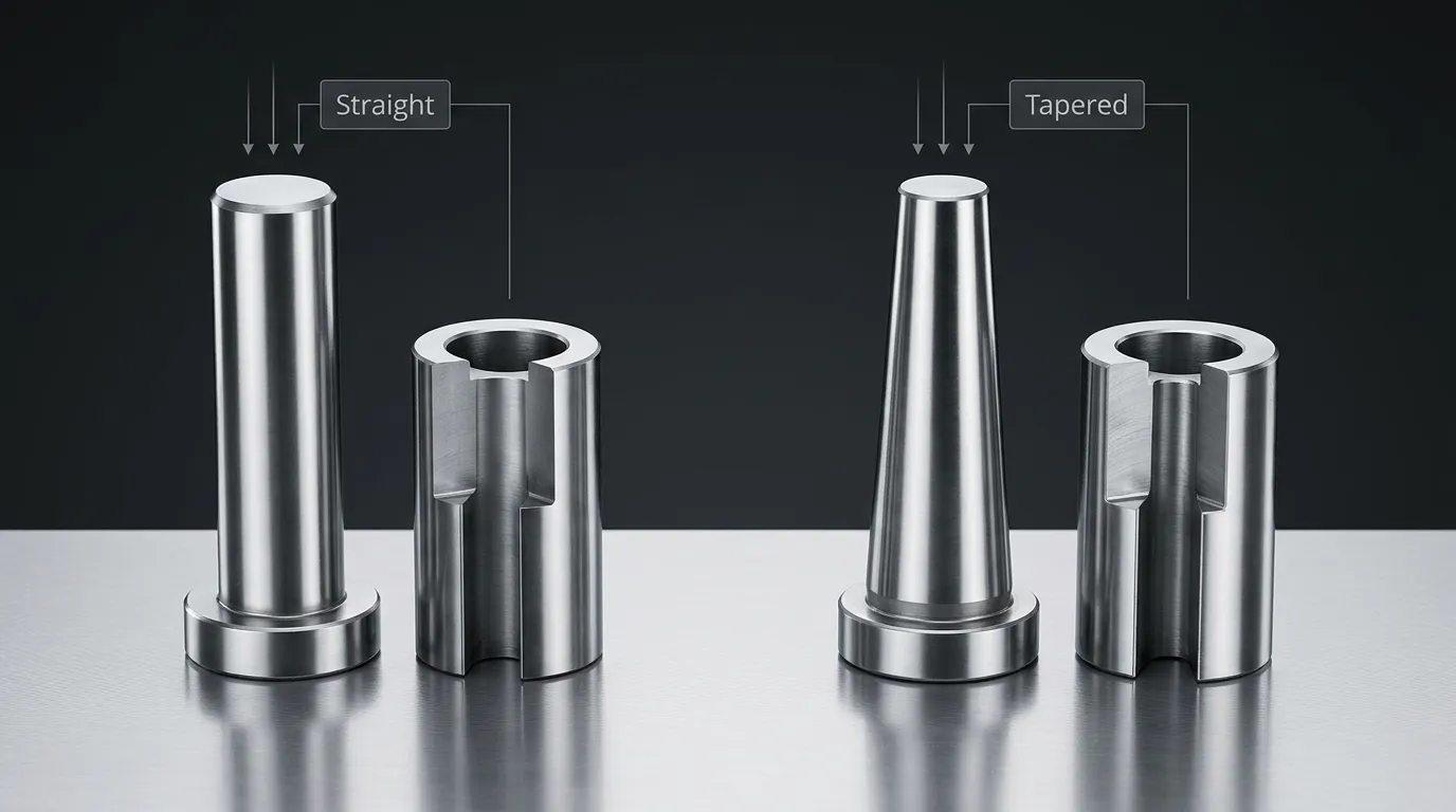
Zestawy pozycjonowania prostego i stożkowego na pierwszy rzut oka
The comparison should cover the complete pin-and-bushing pair, not only the visible pin shape.
| Czynnik porównawczy | Zestaw pozycji prostej | Zestaw pozycjonowania stożkowego |
|---|---|---|
| Geometria lokalizująca | Równoległa lub cylindryczna powierzchnia lokalizująca | Stożkowa lub zwężająca się powierzchnia lokalizująca |
| Zachowanie wejściowe | Wchodzi z niemal stałym prześwitem | Prześwit stopniowo maleje podczas wejścia |
| Wymóg podejścia | Zazwyczaj wymaga dobrze kontrolowanego wcześniejszego wybicia | Może przechwycić ograniczoną ilość przesunięcia podejścia |
| Ostateczne pozycjonowanie | Zależy głównie od dopasowania i ustawienia pin-tuleja | Determined by taper geometry, seating position, and mating accuracy |
| Warunek zamknięcia | Niektóre konstrukcje wymagają prześwitu na linii rozdzielania przy pełnym zamknięciu | Niektóre konstrukcje można skonfigurować tak, aby przy zamknięciu miały pełny kontakt stożkowy |
| Główna zaleta | Controlled, repeatable pre-positioning | Progresywne wprowadzanie i przechwytywanie geometryczne |
| Główne ograniczenie | Może się zablokować, jeśli ściśle dopasowane części wchodzą poza osią | Może się zaklinować lub rozwinąć nierówny kontakt, jeśli ustawienie jest nieprawidłowe |
| Warunki najlepszego dopasowania | Stabilny system prowadzący i przewidywalne podejście do formy | Potrzeba kontrolowanej korekty podczas ostatecznego starcia |
| Trudność modernizacji | Wymiana musi zachować dopasowanie i położenie osi | Conversion requires review of taper, Miejsca siedzące, Montaż, and mating geometry |
A straight system is not merely a tapered system without an angle. The geometry changes how the components enter, where contact develops, and how positional error is transferred into the mold plates.
Jak każda geometria się zazębia, gdy forma się zamyka
The mold’s leader pins and guide bushings normally control the initial movement of the two mold halves. Positioning pins act later in the closing sequence, refining plate location before sensitive features make full contact.
Typowa sekwencja to:
- The leader pins enter their guide bushings and establish the general closing path.
- The positioning pin begins entering its mating bushing.
- The positioning set reduces the remaining lateral movement between the plates.
- Piny rdzeniowe, Wkładki, shutoffs, or other close-clearance features reach their final engagement.
- The mold reaches its designed closed condition.
This sequence matters because positioning components should normally control plate location before delicate features are forced to absorb misalignment. MISUMI’s mold-component documentation, na przykład, describes positioning sets intended to engage before core pins and also notes the need for an appropriate precision leader-pin system. Exact timing still depends on the specific mold design and selected component set.
Główna funkcja naprowadzania należy do Sworznie prowadzące formę. Positioning pins supplement that guidance near final closure; they should not be expected to correct a damaged guide system, severe platen movement, or major mold-base error.
Jak aktywuje się zestaw pozycji prostej
A straight positioning pin enters a cylindrical mating bore. Because the locating surfaces remain parallel, the available entry clearance does not progressively increase toward the tip in the same way as a full tapered locating interface.
This makes prior alignment important. When the leader-pin system has already brought the mold plates close to their intended axes, a straight positioning set can provide controlled and repeatable pre-positioning. The final movement between the pin and bushing depends heavily on their specified fit.
The same close fit that improves positional control can also increase sensitivity to:
- Wejście poza osią
- Zanieczyszczenie tulejki
- Uszkodzone lub wypukłe krawędzie
- Nieprawidłowa koncentryczność
- Ruch termiczny lub strukturalny
- Redundantne punkty lokalizacyjne, które nadmiernie ograniczają płyty
Some catalog straight positioning systems require a small parting-line clearance when the mold is fully closed. That requirement prevents the positioning components from unintentionally carrying closure load or interfering with full plate contact. It is product-specific and must be taken from the selected supplier’s drawing rather than treated as a universal value.
Jak działa zestaw ustawiający się ze stożkowym ustawieniem
A tapered pin enters a matching tapered bushing or seat. At the beginning of engagement, the smaller leading section provides more room for entry. As the mold continues to close, the available radial clearance decreases and the taper progressively guides the mating components toward a common axis.
This progressive capture is the main reason to consider a tapered system. It can tolerate a limited amount of initial offset that might cause edge contact in a close straight interface.
Final performance, jednak, depends on more than the presence of a taper. The designer must control:
- Kąt stożenia lub stosunek stożenia
- Osiowa pozycja siedząca
- Koncentryczność między cechami lokalizującymi i montażowymi
- Długość zaangażowania
- Dystrybucja kontaktowa
- Stan linii rozdzielczej
- Metoda retencji i usuwania
Some supplier systems can be arranged to reach full taper contact or zero clearance at mold closure. That behavior applies only to the documented design. It should not be generalized to every tapered positioning pin.
If the taper seats too deeply, uses incompatible mating angles, or enters under excessive offset, it may create wedging, Nierówny kontakt, difficult release, or unwanted load on the mold plates.
Kryteria selekcji, które faktycznie decydują o lepszym dopasowaniu
The pin shape should not be selected in isolation. The mold’s approach behavior and final positioning requirement are more important than a general preference for straight or tapered components.
| Kryterium wyboru | Prosty jest zwykle preferowany, gdy... | Zwykle preferuje się zwężanie, gdy... |
| Ustawienie podejścia początkowego | System sworzni lider-pin już ściśle kontroluje osie | Ograniczone przesunięcie podejścia musi być rejestrowane stopniowo |
| Ostateczny wymóg pozycyjny | Określone cylindryczne dopasowanie może zapewnić wymaganą kontrolę | Ostateczna lokalizacja ustalana jest poprzez kontrolowane ustawianie siedzenia |
| Wrażliwe cechy pleśni | Przed aktywacją rdzeni lub wkładek konieczne jest wcześniejsze ustawienie | Konieczna jest stopniowa korekta przed kontaktem zacięć lub zamkniętymi elementami |
| Czułość wejściowa | Wejście poza osią jest minimalne i przewidywalne | Potrzebne jest pewne wprowadzenie do krawędzi, aby ograniczyć nagły kontakt krawędzi |
| Warunek zamknięcia | Wymagany prześwit operacyjny lub odstępowy można utrzymać | Zachowanie pełnego siedzenia można zdefiniować i kontrolować |
| Ryzyko do zarządzania | Oprawa i punktacja | Splot i nierówny kontakt stożkowy |
| Sterowanie montażem | Osie sworzniowe i tulejowe można dokładnie trzymać | Oś stożenia i osiowe siedzenie można utrzymać dokładnie |
| Strategia zastępowania | Bezpośrednia cylindryczna wymiana jest praktyczna | Można odtworzyć dopasowaną geometrię stożka i osadzenie |
| Dostępność komponentów | Istnieje odpowiedni standardowy zestaw prostych | Istnieje odpowiedni standardowy zestaw stożków lub uzasadniony jest niestandardowy projekt |
The decision also depends on whether the required component exists as a standard catalog item. Where diameter, Zwężanie, Montaż, Utrzymanie, or engagement conditions fall outside standard ranges, a drawing-based part may be necessary. SunshinePro states that it supplies both standard components and non-standard mold parts processed from customer drawings. Its broader guidance on Standardowe części formy can help separate catalog selection from customization.
Kiedy zestaw prostych pozycji jest lepszym wyborem
A straight positioning system is generally the stronger candidate when the mold’s initial guidance is already stable.
Typical conditions include:
- The leader pins and guide bushings keep plate approach error low.
- The positioning set needs to establish a close, repeatable location before core pins engage.
- The designer can specify and inspect the cylindrical pin-to-bushing fit.
- Parting-line clearance requirements are known.
- Mounting bores and locating axes can be held concentric.
- Contamination and off-axis impact can be controlled.
- Replacement components can reproduce the original fit.
Consider a mold containing several delicate core pins that enter close-clearance holes near the end of closure. If the main guide system already brings the two mold halves into reliable alignment, a straight positioning set can refine their location before those core pins enter.
The design becomes less suitable when significant lateral error remains at the start of positioning engagement. A close straight fit should not be used as a substitute for correcting damaged leader pins, worn guide bushings, or mislocated mounting bores.
Kiedy lepszym wyborem jest zestaw pozycjonowania stożkowego
A tapered positioning system is generally more appropriate when the mold needs a controlled lead-in before reaching its final position.
Typical conditions include:
- Limited approach variation remains after the main guide system engages.
- The mold needs progressive rather than abrupt correction.
- The taper can engage before sensitive shutoffs, Wkładki, or cores reach contact.
- Taper angle, axial seating, and contact position can be defined accurately.
- The design can prevent excessive seating force.
- Removal access is available if the taper becomes tightly seated.
- The selected supplier can reproduce the complete mating geometry.
A tapered system may be useful when two plates approach with a small lateral offset that is acceptable at the start of engagement but must be reduced before a close shutoff meets its mating surface. The taper introduces correction gradually as engagement increases.
That does not mean a tapered pin can repair a poorly guided mold. Its capture range is limited by the actual geometry. Forcing a taper to correct excessive offset can concentrate load on one side of the pin and bushing, damage the contact surfaces, or shift stress into the surrounding mold plate.
Ryzyka, Failure Modes, and Retrofit Mistakes
Straight and tapered systems fail in different ways, although both are sensitive to poor mounting, Zanieczyszczenie, zużycie, and incorrect engagement order.
| Ryzyko | Prawdopodobna przyczyna | Możliwy wynik | Odpowiedź projektowa |
| Oprawy proste | Ciasne dopasowanie połączone z wejściem poza osią | Jamming, Punktacja, plate damage | Poprawa wcześniejszych wskazówek i weryfikacja zezwolenia na działanie |
| Obciążenie krawędzi | Źle ustawiony sworzeń styka się z krawędzią tulejki | Lokalne ubrania, odpryskiwanie, deformacja | Przejrzyj czas zaangażowania i lokalizację osi |
| Klinowanie stożkowe | Nadmierne osiowe osiadła lub nieodpowiednia geometria stożka | Difficult opening, unwanted preload | Dokładnie zdefiniuj osiowy stop i stożek łączący |
| Nierówny kontakt stożkowy | Kąt, Koncentryczność, or mounting error | Lokalne zużycie i słaba ostateczna lokalizacja | Sprawdź geometrię stożka i punkty odniesienia montażu |
| Galling lub punktacja | Poor finish, material pairing, Smarowanie, lub zanieczyszczenie | Nierówne ruchy i przyspieszone zużycie | Określ powierzchnie styku i warunki utrzymania |
| Prześlep wywołany zużyciem | Powtarzający się kontakt i niewystarczające wsparcie | Zwiększone ruchy pozycyjne | Zdefiniuj kryteria inspekcji i wymiany |
| Przedwczesny kontakt z obiektem | Zestaw pozycjonowania aktywuje się zbyt późno | Damage to cores, Wkładki, or shutoffs | Popraw sekwencję zaangażowania |
| Trudne usuwanie komponentów | Brak funkcji wyciągania ani dostępu tylnego | Dłuższa konserwacja i ryzyko uszkodzenia płyty | Uwzględnij demontaż zaczepów lub planowany dostęp do serwisu |
One of the most common design mistakes is treating straight and tapered positioning sets as interchangeable.
Changing a straight pin to a tapered pin affects the mating bushing, installation depth, axial seating, Wzór kontaktowy, parting-line condition, and removal method. The surrounding mold plate may also need different machining. A retrofit should therefore be reviewed as a system change, not a simple pin substitution.
Jest też odwrotnie. Replacing a tapered system with a straight fit may remove the original lead-in and make the mold more sensitive to approach error.
Co musi określać rysunek i RFQ
A supplier cannot evaluate a positioning system accurately from pin diameter alone. The drawing or request for quotation should define the complete mating arrangement.
Zawiera:
- Geometria pozycjonowania prostego lub stożkowego
- Wymiary pinu i tulejki
- Długość zaangażowania
- Taper angle or ratio, tam, gdzie ma zastosowanie
- Planowane dopasowanie lub ostateczny stan siedzenia
- Wymagany prześwit na linii rozdzielczej
- Boki montażu sworzni i tulejów
- Retention method
- Osiowe siedzenie lub miejsce zatrzymania
- Demontaż kranu lub dostępu do wyciągania
- Wymagania materialne
- Wymagania dotyczące obróbki cieplnej i twardości
- Wymagania dotyczące wykończenia powierzchni
- Krytyczna koncentryczność i tolerancje wymiarowe
- Ilość
- Wymóg dopasowanego zbioru lub wymiany wymiennej
- Wymiary inspekcyjne
- Wymogi dotyczące raportu inspekcyjnego
- Relevant operating temperature, Zanieczyszczenie, Załadunek, or maintenance conditions
The pin and bushing should be treated as a mating system. Ask whether replacement components are individually interchangeable or whether the supplier expects them to remain a matched pair.
Detailed tolerance selection belongs in the component drawing and supplier review. Generic fit assumptions are risky because a straight sliding fit, a close positioning fit, and a fully seated taper behave differently during mold closure.
SunshinePro states that it can process non-standard mold parts from customer drawings. The company also describes raw-material inspection, Monitorowanie w trakcie procesu, Testy końcowe, and inspection reporting on its quality page. Those statements support asking about drawing review and critical inspection dimensions, but the exact process, tolerancja, Materiał, and report for a specific positioning set still need written confirmation.
Ostateczna zasada wyboru
Choose a straight positioning set when the mold already has controlled approach guidance and needs close, repeatable pre-positioning.
Choose a tapered positioning set when limited approach offset must be captured progressively and the taper’s seating condition can be controlled.
Review another alignment solution when the mold has severe lateral movement, damaged guide components, major platen problems, or loads beyond what a positioning set should correct.
The better design is the one that matches the complete closing sequence, not the pin shape that appears more precise in isolation.
Przygotowanie rysunku komponentu pozycjonującego do przeglądu dostawcy
Before requesting a quotation, prepare a drawing that shows both sides of the mating system and identifies the functional datums. Include the mold-closing direction, engagement position, final closure condition, and any sensitive features that must be protected before contact.
A useful supplier submission should contain:
- Rysunki sworzni i tulejów
- Odpowiednie szczegóły montażu płyty formowej
- Required fit, Dostęp, or taper seating
- Materiał, Twardość, Zakończenie, oraz wymagania inspekcyjne
- Oczekiwane warunki wymiany i wymienności
SunshinePro offers standard and tailored mold-component solutions and accepts drawing-based non-standard part inquiries. For a straight or tapered positioning system, use the Strona kontaktowa to submit the complete mating design and request confirmation of manufacturability, critical inspection points, oraz strategia wymiany.
Udostępnij:



Napisane przez Sunshine
W Sunshine, Jesteśmy profesjonalnym producentem i dostawcą komponentów do precyzyjnych form, oferując szeroką gamę produktów do tłoczenia i formowania wtryskowego. Naszym głównym celem są formy do dziurkania, Sworznie wyrzutowe i tuleje, oraz słupy i tuleje. Dzięki zaawansowanej obróbki CNC, Ścisła kontrola jakości, oraz silne możliwości produkcyjne, Zapewniamy niezawodność, Części o wysokiej precyzji, wraz ze standardowymi komponentami dostępnymi na stanie, zapewniającymi szybkie i efektywne globalne dostawy.
WIADOMOŚCI
UZYSKAJ USŁUGĘ
Z wysokiej jakości częściami dostosowanymi do każdego budżetu oraz przyjaznym personelem przeszkolonym, by Twoja wizyta była poinformowana i bezproblemowa.
